Installing the coupled bonding conductor
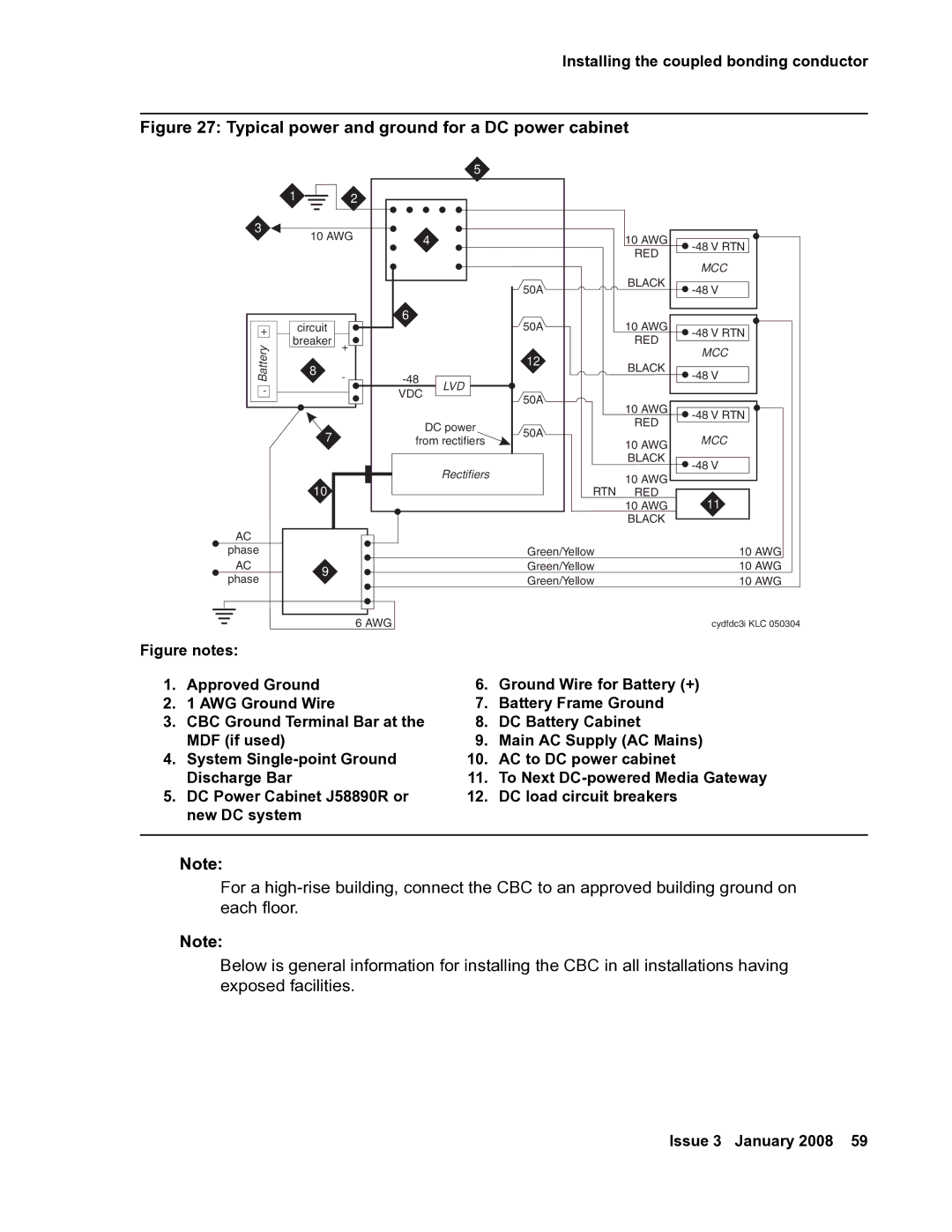
Figure 27: Typical power and ground for a DC power cabinet
|
|
|
| 5 |
|
|
| 1 | 2 |
|
|
|
|
3 | 10 AWG |
| 4 |
| 10 AWG | |
|
|
| ||||
|
|
|
|
|
| RED |
|
|
|
|
| 50A | BLACK |
|
|
|
|
|
| |
| circuit |
| 6 |
| 50A | 10 AWG |
+ | + |
|
| |||
Battery | breaker |
|
|
| RED | |
8 | - |
| 12 | BLACK | ||
|
|
|
| |||
|
|
|
|
| ||
- |
|
| VDC | LVD |
|
|
|
|
| 50A |
| ||
|
|
|
|
| ||
|
|
|
|
| 10 AWG | |
|
|
|
|
|
| |
|
|
|
| DC power | 50A | RED |
| 7 |
|
|
| ||
|
| from rectifiers | 10 AWG | |||
|
|
| ||||
|
|
|
|
|
| |
|
|
|
|
|
| BLACK |
|
|
|
| Rectifiers |
| 10 AWG |
| 10 |
|
|
| RTN | |
|
|
|
| RED | ||
|
|
|
|
|
| 10 AWG |
|
|
|
|
|
| BLACK |
AC |
|
|
|
|
|
|
phase |
|
|
|
| Green/Yellow |
|
AC | 9 |
|
|
| Green/Yellow |
|
phase |
|
|
| Green/Yellow |
| |
|
|
|
|
| ||
![]()
MCC
![]()
![]()
![]()
MCC
![]()
![]()
![]()
MCC
![]()
11
10 AWG
10 AWG
10 AWG
|
|
|
|
| 6 AWG |
| cydfdc3i KLC 050304 |
|
|
|
|
|
| ||
Figure notes: |
|
| |||||
1. | Approved Ground | 6. | Ground Wire for Battery (+) | ||||
2. | 1 AWG Ground Wire | 7. | Battery Frame Ground | ||||
3. | CBC Ground Terminal Bar at the | 8. | DC Battery Cabinet | ||||
| MDF (if used) | 9. | Main AC Supply (AC Mains) | ||||
4. | System | 10. | AC to DC power cabinet | ||||
| Discharge Bar | 11. | To Next | ||||
5. | DC Power Cabinet J58890R or | 12. | DC load circuit breakers | ||||
| new DC system |
|
| ||||
|
|
|
|
|
|
|
|
Note:
For a
Note:
Below is general information for installing the CBC in all installations having exposed facilities.
Issue 3 January 2008 59