Installing and wiring telephones and trunks
4.Connect emergency transfer power
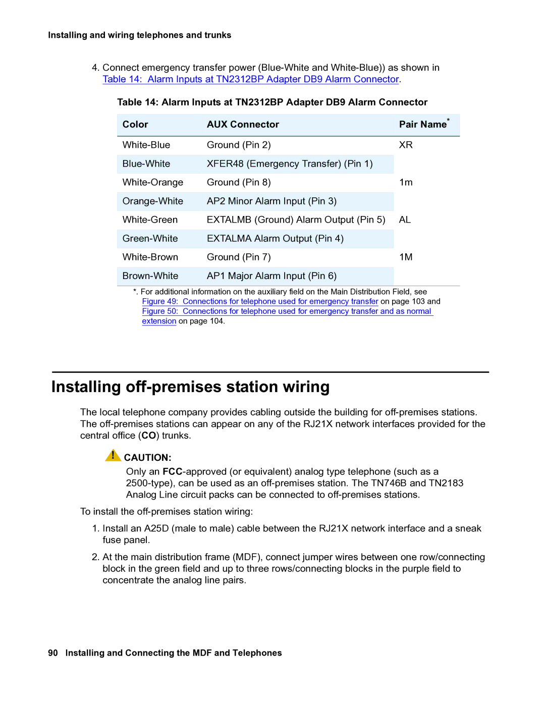
Table 14: Alarm Inputs at TN2312BP Adapter DB9 Alarm Connector
Color | AUX Connector | Pair Name* |
Ground (Pin 2) | XR | |
|
|
|
XFER48 (Emergency Transfer) (Pin 1) |
| |
|
|
|
Ground (Pin 8) | 1m | |
|
|
|
AP2 Minor Alarm Input (Pin 3) |
| |
|
|
|
EXTALMB (Ground) Alarm Output (Pin 5) | AL | |
|
|
|
EXTALMA Alarm Output (Pin 4) |
| |
|
|
|
Ground (Pin 7) | 1M | |
|
|
|
AP1 Major Alarm Input (Pin 6) |
| |
|
|
|
*. For additional information on the auxiliary field on the Main Distribution Field, see Figure 49: Connections for telephone used for emergency transfer on page 103 and Figure 50: Connections for telephone used for emergency transfer and as normal extension on page 104.
Installing off-premises station wiring
The local telephone company provides cabling outside the building for
![]() !
!![]() CAUTION:
CAUTION:
Only an
To install the
1.Install an A25D (male to male) cable between the RJ21X network interface and a sneak fuse panel.
2.At the main distribution frame (MDF), connect jumper wires between one row/connecting block in the green field and up to three rows/connecting blocks in the purple field to concentrate the analog line pairs.