Testing the complete configuration
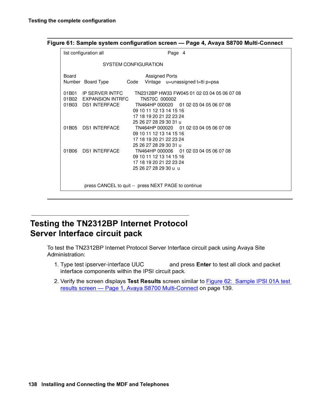
Figure 61: Sample system configuration screen — Page 4, Avaya S8700 Multi-Connect
| list configuration all |
|
|
|
|
|
| Page 4 |
| ||
|
|
| SYSTEM CONFIGURATION |
|
|
|
|
|
|
| |
| Board | Board Type | Code | Vintage |
| Assigned Ports |
|
| |||
| Number | u=unassigned t=tti p=psa |
| ||||||||
| 01B01 | IP SERVER INTFC | TN2312BP | HW33 FW045 | 01 02 03 04 05 06 07 | 08 |
| ||||
| 01B02 | EXPANSION INTRFC | TN570C | 000002 | 01 02 03 04 05 06 07 | 08 |
| ||||
| 01B03 | DS1 INTERFACE | TN464HP | 000020 |
| ||||||
|
|
|
|
| 09 | 10 11 12 | 13 |
| 14 15 | 16 |
|
|
|
|
|
| 17 | 18 19 20 | 21 |
| 22 23 | 24 |
|
| 01B05 | DS1 INTERFACE | TN464HP | 000020 | 25 | 26 27 28 | 29 |
| 30 31 | u |
|
| 01 02 03 04 05 06 07 | 08 |
| ||||||||
|
|
|
|
| 09 | 10 11 12 | 13 |
| 14 15 | 16 |
|
|
|
|
|
| 17 | 18 19 20 | 21 |
| 22 23 | 24 |
|
| 01B06 | DS1 INTERFACE | TN464HP | 000006 | 25 | 26 27 28 | 29 |
| 30 31 | u |
|
| 01 02 03 04 05 06 07 | 08 |
| ||||||||
|
|
|
|
| 09 | 10 11 12 | 13 |
| 14 15 | 16 |
|
|
|
|
|
| 17 | 18 19 20 | 21 |
| 22 23 | 24 |
|
|
|
|
|
| 25 26 27 28 29 | 30 u | u |
| |||
|
| press CANCEL to quit | press NEXT PAGE to continue |
|
|
| |||||
|
|
|
|
|
|
|
|
|
|
|
|
Testing the TN2312BP Internet Protocol
Server Interface circuit pack
To test the TN2312BP Internet Protocol Server Interface circuit pack using Avaya Site Administration:
1.Type test
2.Verify the screen displays Test Results screen similar to Figure 62: Sample IPSI 01A test results screen — Page 1, Avaya S8700