MDF connections to stations and the public switched telephone network
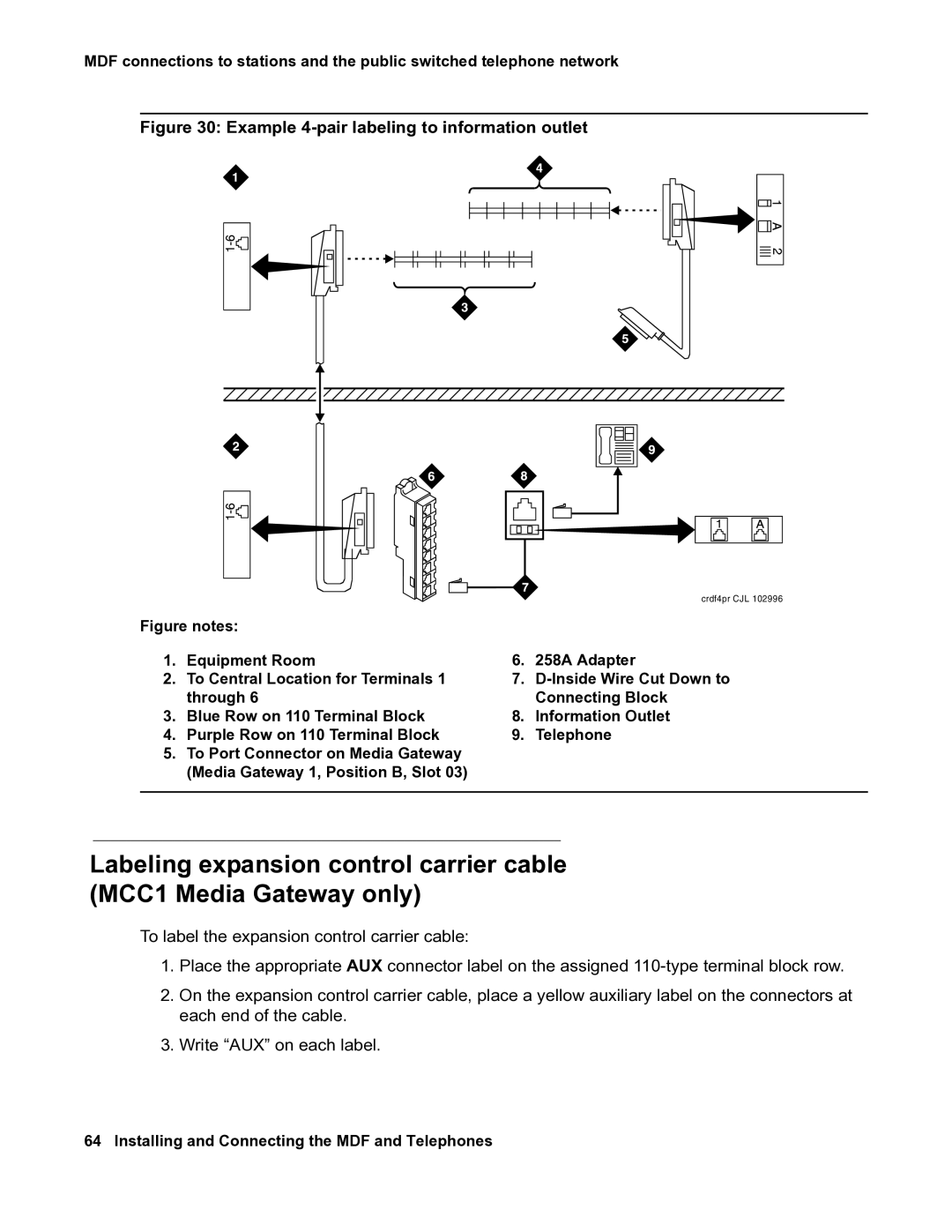
Figure 30: Example 4-pair labeling to information outlet
crdf4pr CJL 102996
Figure notes:
1. | Equipment Room | 6. | 258A Adapter |
2. | To Central Location for Terminals 1 | 7. |
|
| through 6 |
| Connecting Block |
3. | Blue Row on 110 Terminal Block | 8. | Information Outlet |
4. | Purple Row on 110 Terminal Block | 9. | Telephone |
5.To Port Connector on Media Gateway (Media Gateway 1, Position B, Slot 03)
Labeling expansion control carrier cable (MCC1 Media Gateway only)
To label the expansion control carrier cable:
1.Place the appropriate AUX connector label on the assigned
2.On the expansion control carrier cable, place a yellow auxiliary label on the connectors at each end of the cable.
3.Write “AUX” on each label.