Installing and wiring telephones and trunks
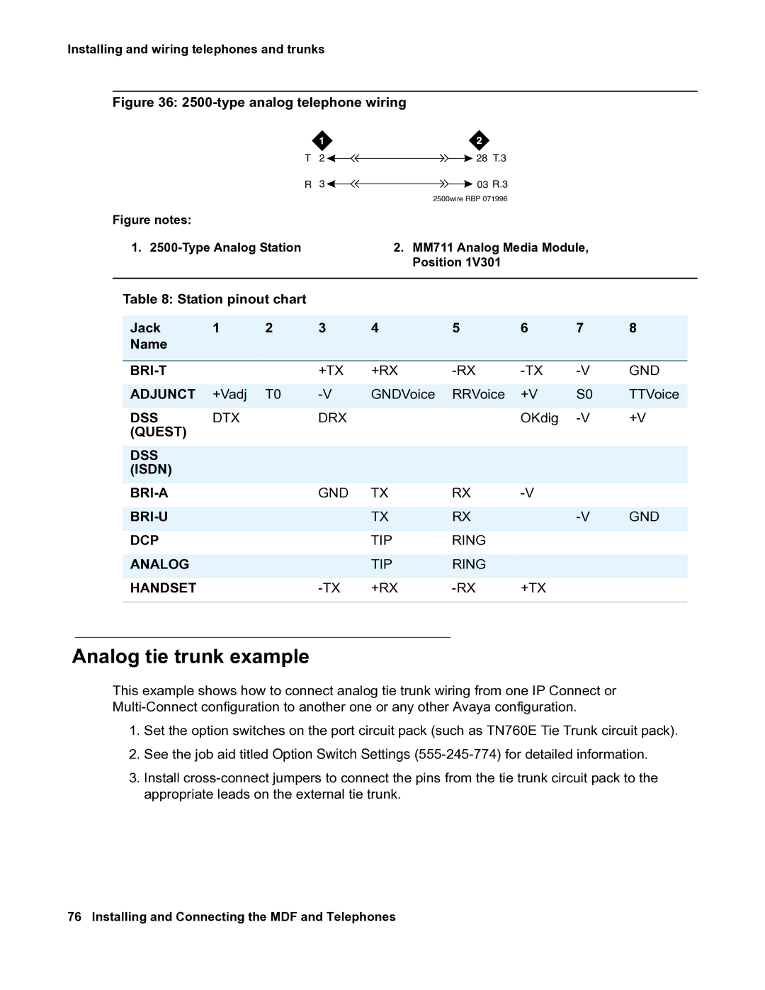
Figure 36: 2500-type analog telephone wiring
|
|
| T | 2 |
| 28 T.3 |
|
|
|
|
|
|
| R | 3 |
| 03 R.3 |
|
|
|
|
|
|
|
|
| 2500wire RBP 071996 |
|
|
|
| |
Figure notes: |
|
|
|
|
|
|
|
|
| |
| 1. |
| 2. MM711 Analog Media Module, |
|
| |||||
|
|
|
|
| Position 1V301 |
|
|
|
| |
|
|
|
|
|
|
|
|
| ||
| Table 8: Station pinout chart |
|
|
|
|
|
|
| ||
|
|
|
|
|
|
|
|
|
|
|
| Jack | 1 | 2 | 3 | 4 | 5 | 6 | 7 | 8 |
|
| Name |
|
|
|
|
|
|
|
|
|
|
|
|
|
|
|
|
|
|
|
|
|
|
| +TX | +RX | GND | |||||
|
|
|
|
|
|
|
|
|
| |
| ADJUNCT | +Vadj | T0 | GNDVoice | RRVoice | +V | S0 | TTVoice |
| |
|
|
|
|
|
|
|
|
|
|
|
| DSS | DTX |
| DRX |
|
| OKdig | +V | ||
| (QUEST) |
|
|
|
|
|
|
|
|
|
|
|
|
|
|
|
|
|
|
|
|
| DSS |
|
|
|
|
|
|
|
|
|
| (ISDN) |
|
|
|
|
|
|
|
|
|
|
|
| GND | TX | RX |
|
|
| ||
|
|
|
|
|
|
|
|
|
| |
|
|
|
| TX | RX |
| GND |
| ||
|
|
|
|
|
|
|
|
|
|
|
| DCP |
|
|
| TIP | RING |
|
|
|
|
|
|
|
|
|
|
|
|
|
|
|
| ANALOG |
|
|
| TIP | RING |
|
|
|
|
|
|
|
|
|
|
|
|
|
|
|
| HANDSET |
|
| +RX | +TX |
|
|
| ||
|
|
|
|
|
|
|
|
|
|
|
Analog tie trunk example
This example shows how to connect analog tie trunk wiring from one IP Connect or
1.Set the option switches on the port circuit pack (such as TN760E Tie Trunk circuit pack).
2.See the job aid titled Option Switch Settings
3.Install