Installing and wiring telephones and trunks
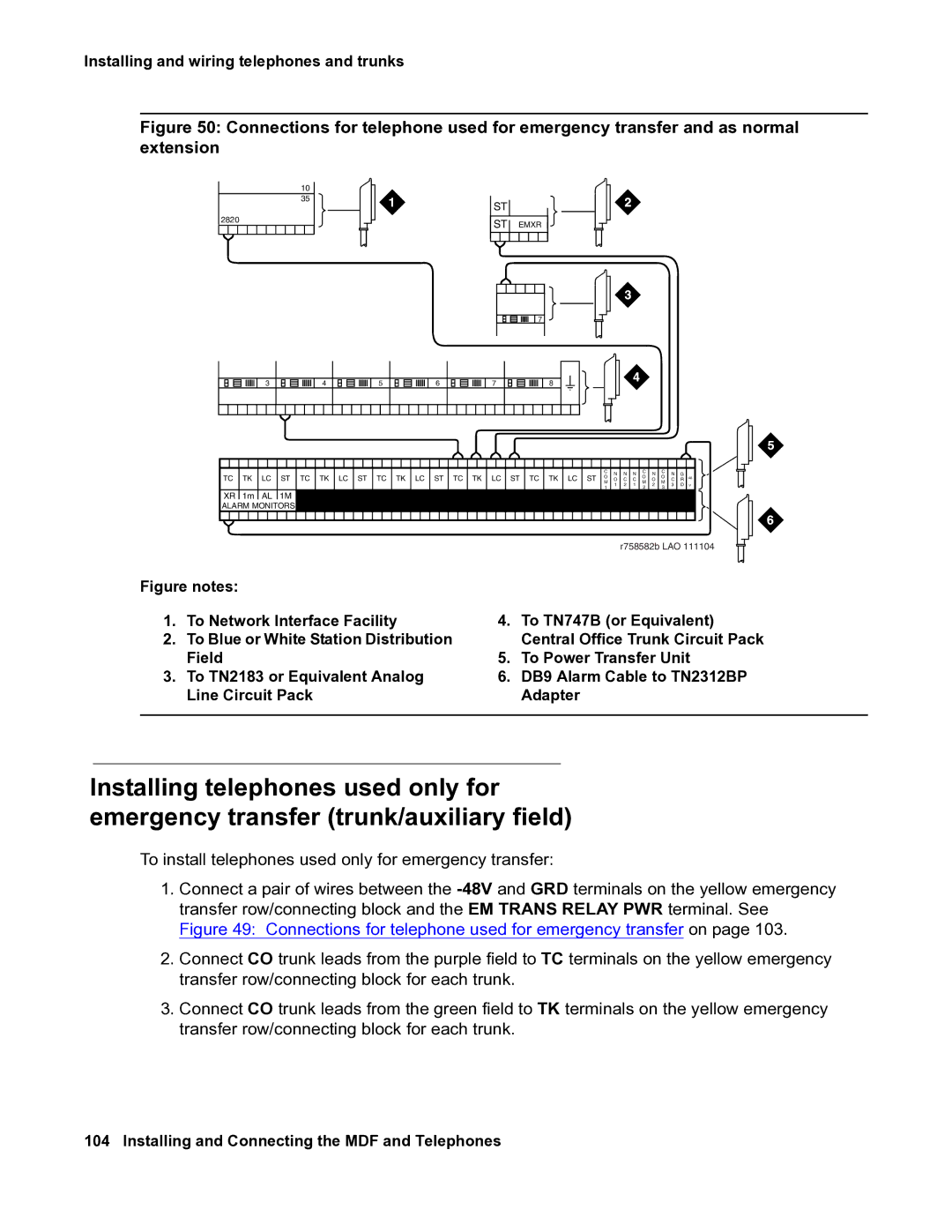
Figure 50: Connections for telephone used for emergency transfer and as normal extension
10
35
2820
3 | 4 |
ST
![]() ST
ST ![]() EMXR
EMXR
![]() 7
7
5 | 6 | 7 | 8 |
|
|
|
|
| C | N | N | N | C | N | C | N | G | |
TC | TK | LC | ST TC TK LC ST TC TK LC ST TC TK LC ST TC TK LC ST | O | O | O | ||||||||
O | C | C | O | C | R | |||||||||
|
|
|
|
| M | 1 | 2 | 1 | M | 2 | M | 3 | D V | |
|
|
|
|
| 1 | 2 | 3 | |||||||
|
|
|
|
|
|
|
|
|
|
| ||||
XR | 1m | AL | 1M |
|
|
|
|
|
|
|
|
|
| |
ALARM MONITORS |
|
|
|
|
|
|
|
|
|
| ||||
Figure notes: |
| r758582b LAO 111104 |
| |
|
|
| ||
|
|
| ||
1. | To Network Interface Facility | 4. | To TN747B (or Equivalent) | |
2. | To Blue or White Station Distribution |
| Central Office Trunk Circuit Pack | |
| Field | 5. | To Power Transfer Unit | |
3. | To TN2183 or Equivalent Analog | 6. | DB9 Alarm Cable to TN2312BP | |
| Line Circuit Pack |
| Adapter | |
|
|
|
|
|
Installing telephones used only for emergency transfer (trunk/auxiliary field)
To install telephones used only for emergency transfer:
1.Connect a pair of wires between the
2.Connect CO trunk leads from the purple field to TC terminals on the yellow emergency transfer row/connecting block for each trunk.
3.Connect CO trunk leads from the green field to TK terminals on the yellow emergency transfer row/connecting block for each trunk.