Connecting telephones
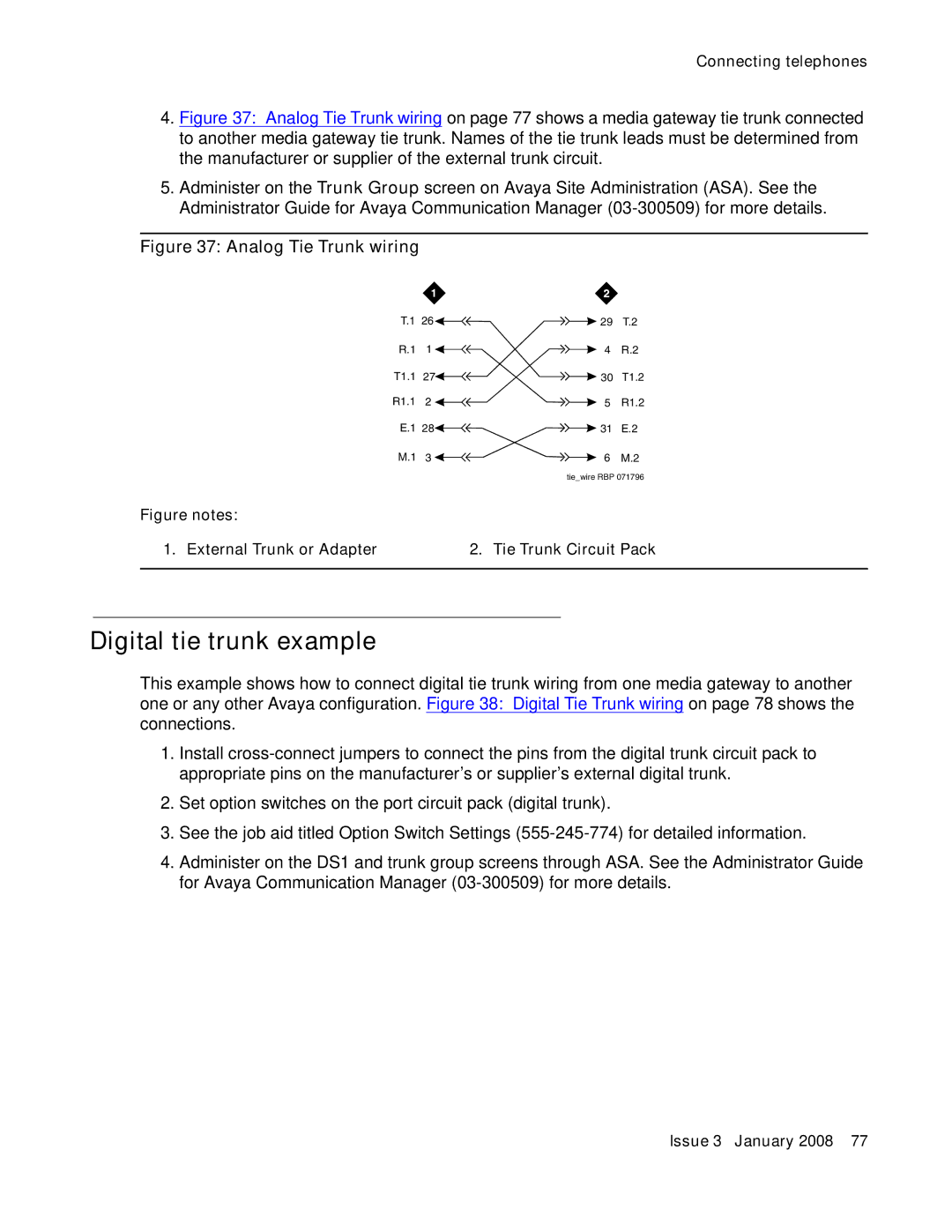
4.Figure 37: Analog Tie Trunk wiring on page 77 shows a media gateway tie trunk connected to another media gateway tie trunk. Names of the tie trunk leads must be determined from the manufacturer or supplier of the external trunk circuit.
5.Administer on the Trunk Group screen on Avaya Site Administration (ASA). See the Administrator Guide for Avaya Communication Manager (03-300509) for more details.
Figure 37: Analog Tie Trunk wiring
T.1 | 26 | 29 | T.2 | |
R.1 | 1 | 4 | R.2 | |
T1.1 | 27 |
| 30 | T1.2 |
| ||||
| ||||
R1.1 | 2 | 5 | R1.2 | |
E.1 | 28 | 31 | E.2 | |
M.1 | 3 | 6 | M.2 | |
| tie_wire RBP 071796 |
Figure notes: |
|
1. External Trunk or Adapter | 2. Tie Trunk Circuit Pack |
|
|
Digital tie trunk example
This example shows how to connect digital tie trunk wiring from one media gateway to another one or any other Avaya configuration. Figure 38: Digital Tie Trunk wiring on page 78 shows the connections.
1.Install
2.Set option switches on the port circuit pack (digital trunk).
3.See the job aid titled Option Switch Settings
4.Administer on the DS1 and trunk group screens through ASA. See the Administrator Guide for Avaya Communication Manager
Issue 3 January 2008 77
