Connecting external alarm indicators and auxiliary power
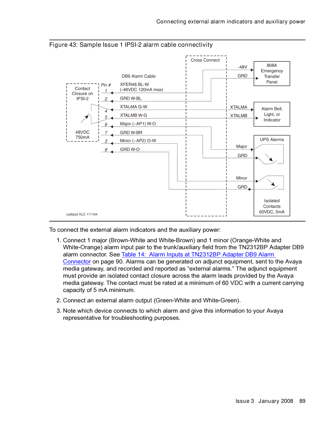
Figure 43: Sample Issue 1 IPSI-2 alarm cable connectivity
Pin #
Contact 1 Closure on
4
5
6
48VDC 7 750mA
3
8
Cross Connect
DB9 Alarm Cable
XFER48
GRD
XTALMA
XTALMB
Major (~AP1)
GRD
Minor (~AP2)
GRD
808A | ||
Emergency | ||
GRD | ||
Transfer | ||
| Panel | |
|
|
XTALMA | Alarm Bell, | |
| ||
XTALMB | Light, or | |
Indicator | ||
| ||
| UPS Alarms | |
Major |
| |
GRD |
| |
Minor |
| |
GRD |
| |
| Isolated | |
| Contacts | |
| 60VDC, 5mA |
cydlips2 KLC 111104
To connect the external alarm indicators and the auxiliary power:
1.Connect 1 major
2.Connect an external alarm output
3.Note which device connects to which alarm and give this information to your Avaya representative for troubleshooting purposes.
Issue 3 January 2008 89