Station circuit distribution from equipment room
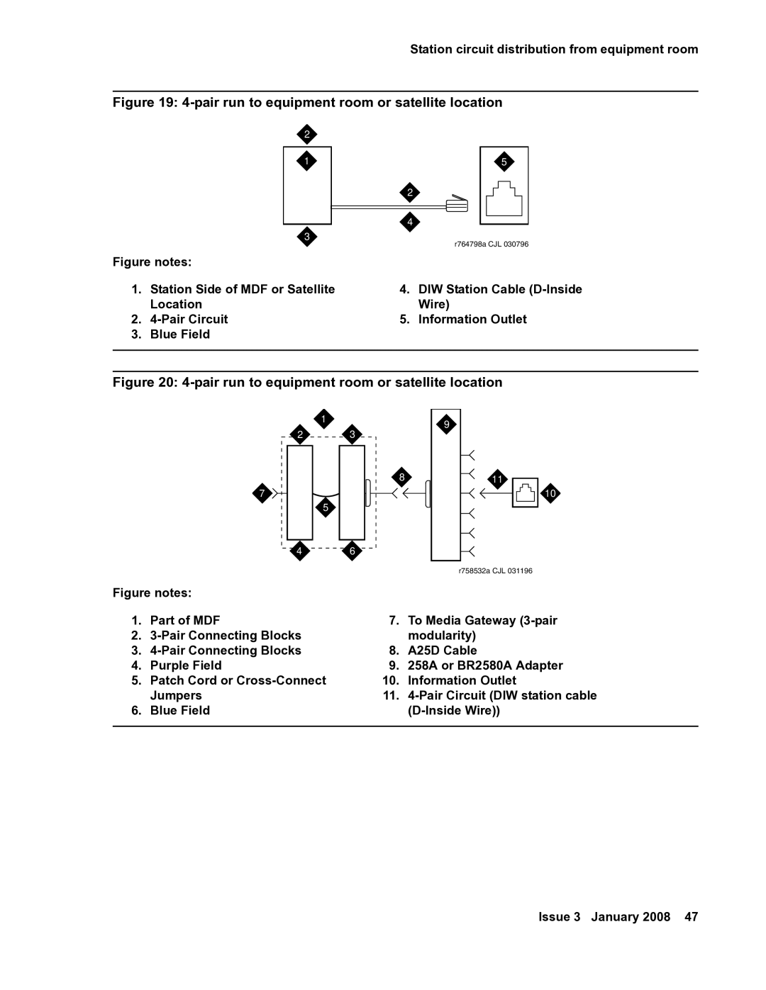
Figure 19: 4-pair run to equipment room or satellite location
| 2 |
|
|
|
| 1 | 5 | ||
|
| 2 |
|
|
|
| 4 |
|
|
|
|
|
| |
|
|
|
| |
| 3 |
| r764798a CJL 030796 | |
|
|
| ||
Figure notes: |
|
|
| |
1. | Station Side of MDF or Satellite | 4. DIW Station Cable | ||
| Location | Wire) | ||
2. |
| 5. Information Outlet | ||
3. | Blue Field |
|
|
|
|
|
|
|
|
Figure 20: 4-pair run to equipment room or satellite location
1
23
7
5
46
Figure notes:
1.Part of MDF
2.3-Pair Connecting Blocks
3.
4.Purple Field
5.Patch Cord or Cross-Connect Jumpers
6.Blue Field
9
8 ![]()
![]() 11
11
10
r758532a CJL 031196
7.To Media Gateway
8.A25D Cable
9.258A or BR2580A Adapter
10.Information Outlet
11.
Issue 3 January 2008 47