1152A1
To connect the 1152A1 Power Distribution Unit:
1.Plug a power cord into the power socket on the rear of the 1152A1 Power Distribution Unit.
2.Plug the other end of the power cord into the power receptacle.
The 1152A1 PDU powers up, and the internal fans begin operating.
The 1152A1 PDU then runs through its Power On Self Test (POST), which takes less than 10 seconds. During the test, all the ports on the unit are disabled and the LEDs light up. For more information on the test, see the user’s guide that comes with the unit.
Connecting the cables
All of the ports on the front of the 1152A1 PDU are configured as data
1 | 2 | 3 | 4 | 5 | 6 | 7 | 8 | 9 | 10 | 11 | 12 | 13 | 14 | 15 | 16 | 17 | 18 | 19 | 20 | 21 | 22 | 23 | 24 |
|
Data & |
|
|
|
|
|
|
|
|
|
|
|
|
|
|
|
|
|
|
|
|
|
| 1152A1 Power | |
Power |
|
|
|
|
|
|
|
|
|
|
|
|
|
|
|
|
|
|
|
|
|
| ||
|
|
|
|
|
|
|
|
|
|
|
|
|
|
|
|
|
|
|
|
|
|
| Distribution Unit | |
|
|
|
|
|
|
|
|
|
|
|
|
|
|
|
|
|
|
|
|
|
|
|
| AC |
Data |
|
|
|
|
|
|
|
|
|
|
|
|
|
|
|
|
|
|
|
|
|
| Console |
|
|
|
|
|
|
|
|
|
|
|
|
|
|
|
|
|
|
|
|
|
|
|
| 48Vdc | |
Use a standard CAT5, CAT6 or CAT6e
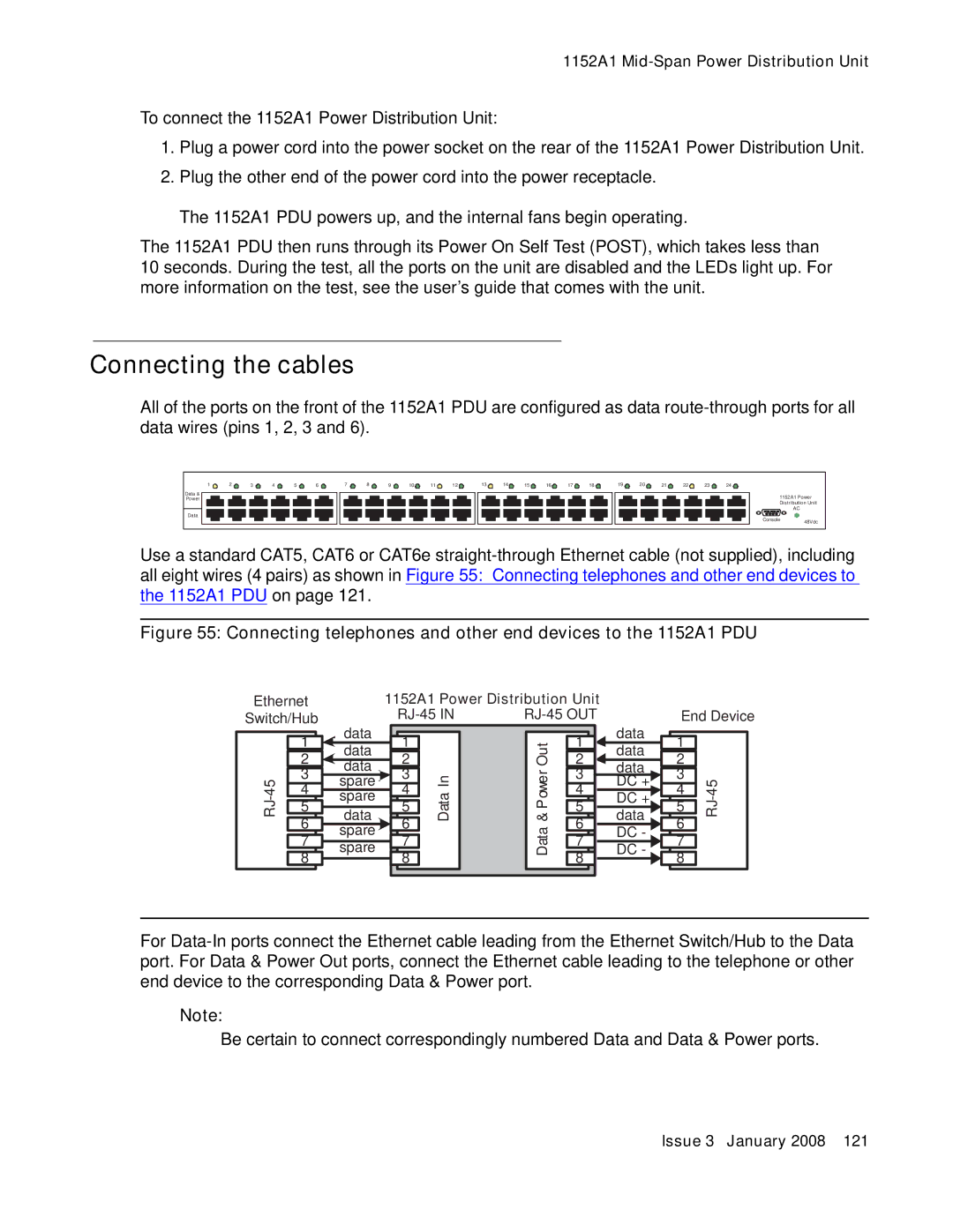
Figure 55: Connecting telephones and other end devices to the 1152A1 PDU
Ethernet
Switch/Hub
1152A1 Power Distribution Unit |
| |
End Device | ||
| 1 | |
| 2 | |
3 | ||
4 | ||
| ||
| 5 | |
| 6 | |
| 7 | |
| 8 |
data
data
data
spare
spare
data
spare
spare
1 |
2 |
3 |
4 |
5 |
6 |
7 |
8 |
Data In
Data & Power Out
1 | data | 1 |
| |
data |
| |||
2 | 2 |
| ||
data |
| |||
3 | 3 |
| ||
DC + | ||||
4 | 4 | |||
DC + | ||||
| ||||
5 | 5 |
| ||
data |
| |||
6 | 6 |
| ||
DC - |
| |||
7 | 7 |
| ||
DC - |
| |||
8 | 8 |
| ||
|
|
For
Note:
Be certain to connect correspondingly numbered Data and Data & Power ports.