Installing and wiring telephones and trunks
See Figure 41: Example adjunct power connections on page 85 and Figure 46: Connections at trunk/auxiliary field on page 96.
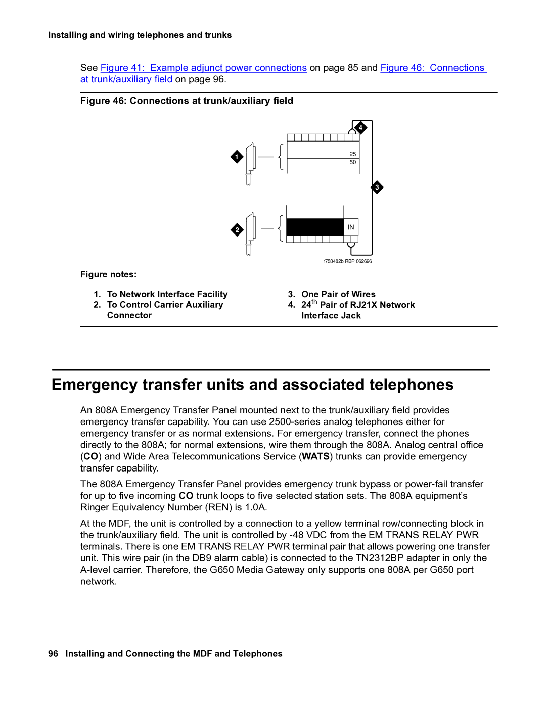
Figure 46: Connections at trunk/auxiliary field
25
50
| | | | | | | IN |
| | | | | | |
| | | | | |
| | | | | | | | | |
| | | | | | |
| | | | | | | | | |
| | | | | | | | | |
| | | | | | r758482b RBP 062696 |
Figure notes: | | | | | | |
1. | To Network Interface Facility | 3. | One Pair of Wires |
2. | To Control Carrier Auxiliary | 4. | 24th Pair of RJ21X Network |
| Connector | | | Interface Jack |
| | | | | | | | | |
Emergency transfer units and associated telephones
An 808A Emergency Transfer Panel mounted next to the trunk/auxiliary field provides emergency transfer capability. You can use 2500-series analog telephones either for emergency transfer or as normal extensions. For emergency transfer, connect the phones directly to the 808A; for normal extensions, wire them through the 808A. Analog central office (CO) and Wide Area Telecommunications Service (WATS) trunks can provide emergency transfer capability.
The 808A Emergency Transfer Panel provides emergency trunk bypass or power-fail transfer for up to five incoming CO trunk loops to five selected station sets. The 808A equipment’s Ringer Equivalency Number (REN) is 1.0A.
At the MDF, the unit is controlled by a connection to a yellow terminal row/connecting block in the trunk/auxiliary field. The unit is controlled by -48 VDC from the EM TRANS RELAY PWR terminals. There is one EM TRANS RELAY PWR terminal pair that allows powering one transfer unit. This wire pair (in the DB9 alarm cable) is connected to the TN2312BP adapter in only the A-level carrier. Therefore, the G650 Media Gateway only supports one 808A per G650 port network.
96 Installing and Connecting the MDF and Telephones