Installing and wiring telephone power supplies
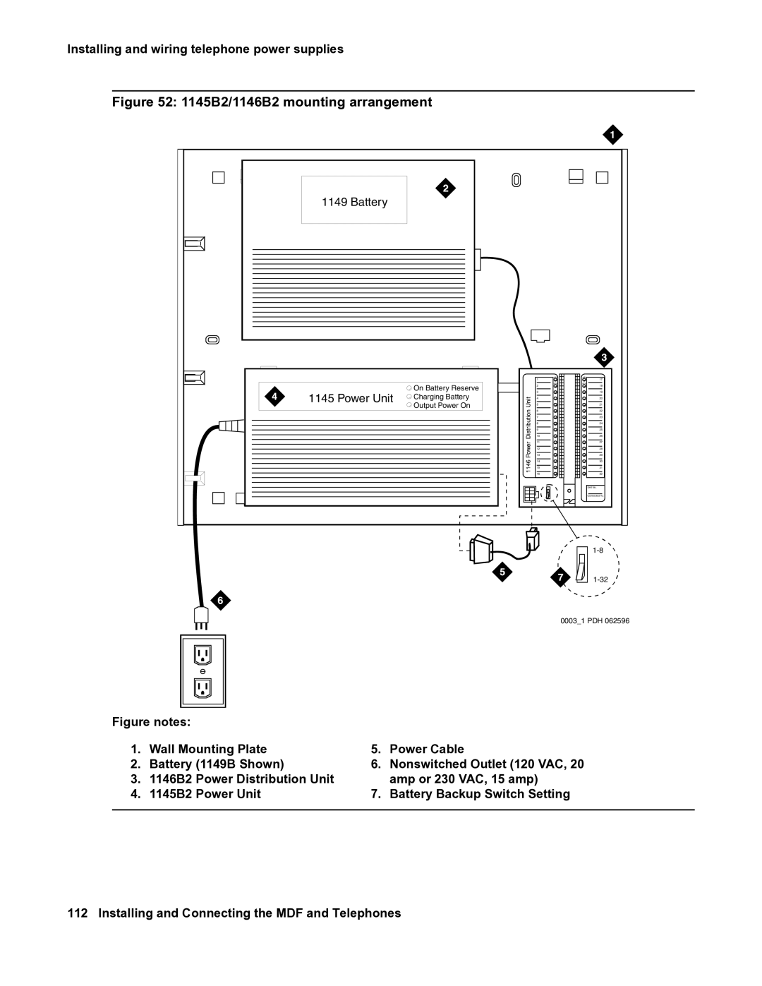
Figure 52: 1145B2/1146B2 mounting arrangement
1149 Battery
On Battery Reserve
1145 Power Unit Charging Battery
Output Power On
1
RTN
2
3
4
5
6
7
8
9
10
11
12
13
14
15
16
17
RTN
18
19
20
21
22
23
24
25
26
27
28
29
30
31
32
Unit No.
Connected To:
0003_1 PDH 062596
Figure notes: |
|
|
| |
1. | Wall Mounting Plate | 5. | Power Cable | |
2. | Battery (1149B Shown) | 6. | Nonswitched Outlet (120 VAC, 20 | |
3. | 1146B2 | Power Distribution Unit |
| amp or 230 VAC, 15 amp) |
4. | 1145B2 | Power Unit | 7. | Battery Backup Switch Setting |
|
|
|
|
|