Media gateway connections to the MDF
Cable routing guidelines
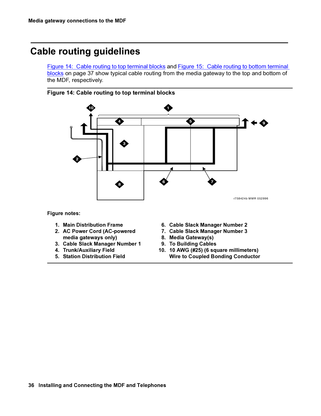
Figure 14: Cable routing to top terminal blocks and Figure 15: Cable routing to bottom terminal blocks on page 37 show typical cable routing from the media gateway to the top and bottom of the MDF, respectively.
Figure 14: Cable routing to top terminal blocks
|
|
| r7 5 8 4 2 4 b M M R 0 5 2 9 9 6 |
Figure notes: |
|
| |
1. | Main Distribution Frame | 6. | Cable Slack Manager Number 2 |
2. | AC Power Cord | 7. | Cable Slack Manager Number 3 |
| media gateways only) | 8. | Media Gateway(s) |
3. | Cable Slack Manager Number 1 | 9. | To Building Cables |
4. | Trunk/Auxiliary Field | 10. | 10 AWG (#25) (6 square millimeters) |
5. | Station Distribution Field |
| Wire to Coupled Bonding Conductor |
|
|
|
|