Omega Engineering FP-6000 Chapter Installation and Wiring, Location of Fitting, Sensor Position

Models: FP-6000

1 32
Download 32 pages 56.58 Kb
Page 8
Image 8

Chapter 2

Installation and Wiring

The linearity and accuracy of the FP-6000 Series sensor depend on predictable flow conditions in the pipe and proper location of the fitting. As with any insertion flow sensor, the pipe must be full and generally free of air pockets.

2.1 Location of Fitting

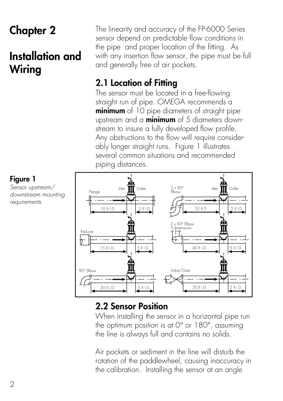
The sensor must be located in a free-flowing straight run of pipe. OMEGA recommends a minimum of 10 pipe diameters of straight pipe upstream and a minimum of 5 diameters down- stream to insure a fully developed flow profile. Any obstructions to the flow will require consider- ably longer straight runs. Figure 1 illustrates several common situations and recommended piping distances.

Figure 1

Sensor upstream/ downstream mounting requirements

Inlet

Outlet

2 x 90°

Inlet

Outlet

Flange


Elbow


10 X I.D.

5 X I.D.

25 X D


5 X I.D.


2 x 90° Elbow


Reducer


3 dimensions


15 X I.D.

5 X I.D.

40 X I.D.


5 X I.D.

90° Elbow


Valve/Gate


20 X I.D.

5 X I.D.

50 X I.D.


5 X I.D.

2.2 Sensor Position

When installing the sensor in a horizontal pipe run the optimum position is at 0° or 180°, assuming the line is always full and contains no solids.

Air pockets or sediment in the line will disturb the rotation of the paddlewheel, causing inaccuracy in the calibration. Installing the sensor at an angle

2

Page 8
Image 8
Omega Engineering FP-6000 manual Chapter Installation and Wiring, Location of Fitting, Sensor Position