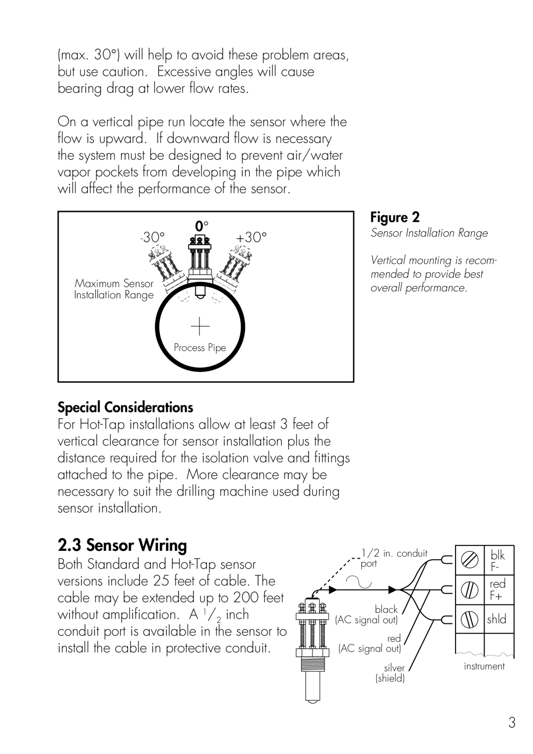
(max. 30°) will help to avoid these problem areas, but use caution. Excessive angles will cause bearing drag at lower flow rates.
On a vertical pipe run locate the sensor where the flow is upward. If downward flow is necessary the system must be designed to prevent air/water vapor pockets from developing in the pipe which will affect the performance of the sensor.
0° | |
+30° |
Maximum Sensor
Installation Range
Process Pipe
Figure 2
Sensor Installation Range
Vertical mounting is recom- mended to provide best overall performance.
Special Considerations
For
2.3 Sensor Wiring
Both Standard and
1/2 in. conduit port
black (AC signal out)
red (AC signal out)
silver (shield)
blk |
F- |
red |
F+ |
shld |
instrument |
3
