PANEL CUTOUT | WIRING GUIDELINES | |
| A) | Measuring Inputs |
| NOTE: Any external components (like Zener di- | |
| odes, etc.) connected between sensor and input | |
| terminals may cause errors in measurement due to | |
| excessive and/or not balanced line resistance or | |
| possible leakage currents. | |
| TC | Input |
| + 10 | |
| _ | 9 |
|
| |
|
| Shield |
| + 10 | |
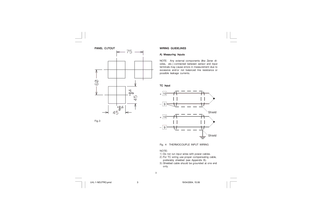
Fig.3 |
|
|
_
9
Shield
Fig. 4 THERMOCOUPLE INPUT WIRING
NOTE:
1)Do not run input wires with power cables.
2)For TC wiring use proper compensating cable, preferably shielded (see Appendix B).
3)Shielded cable should be grounded at one end only.
3
3 | 19/04/2004, 15.06 |
