RTD INPUT | LINEAR INPUT |
 RTD
RTD 
8 ![]()
![]() 9
9 ![]()
![]() 10
10
![]() RTD
RTD ![]()
8 ![]()
![]() 9
9 ![]()
![]() 10
10
10 | + | mA, | |
mV | |||
|
| ||
|
| or | |
9 | _ V | ||
|
| ||
| Shield | ||
10 | + | mA | |
|
| ||
| _ | mV | |
9 | or | ||
| |||
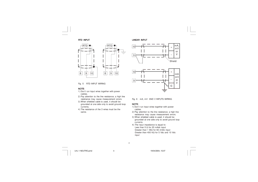
Fig. 5 RTD INPUT WIRING
NOTE:
1)Don’t run input wires together with power cables.
2)Pay attention to the line resistance; a high line resistance may cause measurement errors.
3)When shielded cable is used, it should be grounded at one side only to avoid ground loop currents.
4)The resistance of the 3 wires must be the same.
V |
G |
Fig. 6 mA, mV AND V INPUTS WIRING |
NOTE:
1)Don’t run input wires together with power cables.
2)Pay attention to the line resistance; a high line resistance may cause measurement errors.
3)When shielded cable is used, it should be grounded at one side only to avoid ground loop currents.
4)The input impedance is equal to: Less than 5 Ω for 20 mAdc input Greater than 1 MΩ for 60 mVdc input Greater than 400 KΩ for 5 Vdc and 10 Vdc input
4
4 | 19/04/2004, 15.07 |