Connector signals
∑PARALLEL I/O (50P) connector
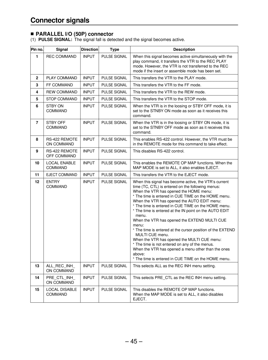
(1) PULSE SIGNAL: The signal fall is detected and the signal becomes active.
Pin no. | Signal | Direction | Type | Description |
|
|
|
|
|
1 | REC COMMAND | INPUT | PULSE SIGNAL | When this signal becomes active simultaneously with the |
|
|
|
| play command, it transfers the VTR to the REC PLAY |
|
|
|
| mode. However, the VTR is not transferred to the REC |
|
|
|
| mode if the insert or assemble mode has been set. |
|
|
|
|
|
2 | PLAY COMMAND | INPUT | PULSE SIGNAL | This transfers the VTR to the PLAY mode. |
|
|
|
|
|
3 | FF COMMAND | INPUT | PULSE SIGNAL | This transfers the VTR to the FF mode. |
|
|
|
|
|
4 | REW COMMAND | INPUT | PULSE SIGNAL | This transfers the VTR to the REW mode. |
|
|
|
|
|
5 | STOP COMMAND | INPUT | PULSE SIGNAL | This transfers the VTR to the STOP mode. |
|
|
|
|
|
6 | STBY ON | INPUT | PULSE SIGNAL | When the VTR is in the loosing or STBY OFF mode, it is |
| COMMAND |
|
| set to the STNBY ON mode as soon as it receives this |
|
|
|
| command. |
|
|
|
|
|
7 | STBY OFF | INPUT | PULSE SIGNAL | When the VTR is in the loosing or STBY ON mode, it is |
| COMMAND |
|
| set to the STNBY OFF mode as soon as it receives this |
|
|
|
| command. |
|
|
|
|
|
8 | INPUT | PULSE SIGNAL | This enables | |
| ON COMMAND |
|
| in the REMOTE mode for this command to take effect. |
|
|
|
|
|
9 | INPUT | PULSE SIGNAL | This disables | |
| OFF COMMAND |
|
|
|
|
|
|
|
|
10 | LOCAL ENABLE | INPUT | PULSE SIGNAL | This enables the REMOTE OP MAP functions. When the |
| COMMAND |
|
| MAP MODE is set to ALL, it also enables EJECT. |
|
|
|
|
|
11 | EJECT COMMAND | INPUT | PULSE SIGNAL | This transfers the VTR to the EJECT mode. |
|
|
|
|
|
12 | ENTRY | INPUT | PULSE SIGNAL | When this signal has become active, the VTR’s current |
| COMMAND |
|
| time (TC, CTL) is entered on the following menus: |
|
|
|
| When the VTR has opened the HOME menu: |
|
|
|
| ≥The time is entered in CUE TIME on the HOME menu. |
|
|
|
| When the VTR has opened the AUTO EDIT menu: |
|
|
|
| ≥The time is entered in CUE TIME on the HOME menu. |
|
|
|
| ≥The time is entered at the IN point on the AUTO EDIT |
|
|
|
| menu. |
|
|
|
| When the VTR has opened the EXTEND MULTI CUE |
|
|
|
| menu: |
|
|
|
| ≥The time is entered at the cursor position of the EXTEND |
|
|
|
| MULTI CUE menu. |
|
|
|
| When the VTR has opened the MULTI CUE menu: |
|
|
|
| ≥The time is not entered on any of the menus. |
|
|
|
| When the VTR has opened a menu other than the ones |
|
|
|
| above: |
|
|
|
| ≥The time is entered in CUE TIME on the HOME menu. |
|
|
|
|
|
13 | ALL_REC_INH_ | INPUT | PULSE SIGNAL | This selects ALL as the REC INH menu setting. |
| ON COMMAND |
|
|
|
|
|
|
|
|
14 | PRE_CTL_INH_ | INPUT | PULSE SIGNAL | This selects PRE_CTL as the REC INH menu setting. |
| ON COMMAND |
|
|
|
|
|
|
|
|
15 | LOCAL DISABLE | INPUT | PULSE SIGNAL | This disables the REMOTE OP MAP functions. |
| COMMAND |
|
| When the MAP MODE is set to ALL, it also disables |
|
|
|
| EJECT. |
|
|
|
|
|
– 45 –
