Controls and their functions
Connector section
~AC IN | FUSE |
| 125V 5A |
| (26) | (27) |
| (28) |
| (29) | (30) |
| ||||||||
| REF IN |
|
|
| VIDEO OUT |
|
| WFM |
| SD SDI |
| HD SDI |
| |||
| HD |
| SD | 1 |
| 2 |
| 3 |
|
|
| IN | OUT1 | IN | OUT | OUT |
|
|
|
|
|
|
|
|
|
|
|
|
|
|
| 1 | 3 |
| ON |
| ON |
|
|
|
| (SUPER) |
|
|
|
|
|
|
| |
| 75Ω | 75Ω |
|
|
|
|
|
| ACTIVE |
| ACTIVE |
|
| |||
|
| CH |
| CH | INPUT | CH |
| CH | THROUGH | THROUGH | OUT |
| ||||
| OFF |
| OFF |
|
| 1 3 |
|
| 5 7 |
|
| OUT2 |
| 2 |
| |
|
|
|
|
|
| 2 4 |
|
|
| 6 8 |
|
|
|
|
|
|
| SD |
|
|
|
|
|
|
|
|
|
|
|
|
|
| MONITOR |
| HD |
| SD |
|
|
|
|
|
|
|
| SPARE | MONITOR |
|
| (SUPER) |
|
|
| CH 1 3 CH | OUTPUT | CH 5 7 CH |
|
|
| ||||||||
|
|
|
|
|
| 2 4 |
|
|
| 6 8 |
|
|
|
|
|
|
| REF OUT |
|
|
|
| DIGITAL AUDIO |
|
|
|
| (SUPER) |
|
|
| ||
|
|
|
|
|
|
|
|
|
|
|
|
| ||||
| REMOTE |
|
|
|
| REMOTE |
|
| REMOTE |
| V/A |
|
| |||
| IN |
|
|
|
| OUT |
|
| IN/OUT |
| CONTROL |
|
| PARALLEL | ||
|
|
|
|
|
|
|
|
|
|
|
|
|
|
|
| IN/OUT |
|
|
|
|
|
|
|
| CONTROL |
|
|
|
| (50P) | |||
|
|
|
|
|
|
|
|
| PANEL |
|
|
|
|
| ||
|
|
| AUDIO IN |
|
|
|
|
|
| TIME CODE |
|
|
|
| ||
| PUSHCH 1 | PUSHCH 2 |
| PUSHCH 3 |
| PUSHCH 4 | PUSHCUE |
|
| PUSHIN |
| OUT |
|
|
| |
|
|
| AUDIO OUT |
|
|
|
|
|
| MONITOR |
|
|
|
| ||
SIGNAL | CH 1 | CH 2 |
| CH 3 |
|
| CH 4 | CUE |
|
| L |
| R |
|
|
|
GND |
|
|
|
|
|
|
|
|
|
|
|
|
|
|
|
|
|
|
|
|
|
|
|
|
|
|
| (31) |
| (32) |
| ||
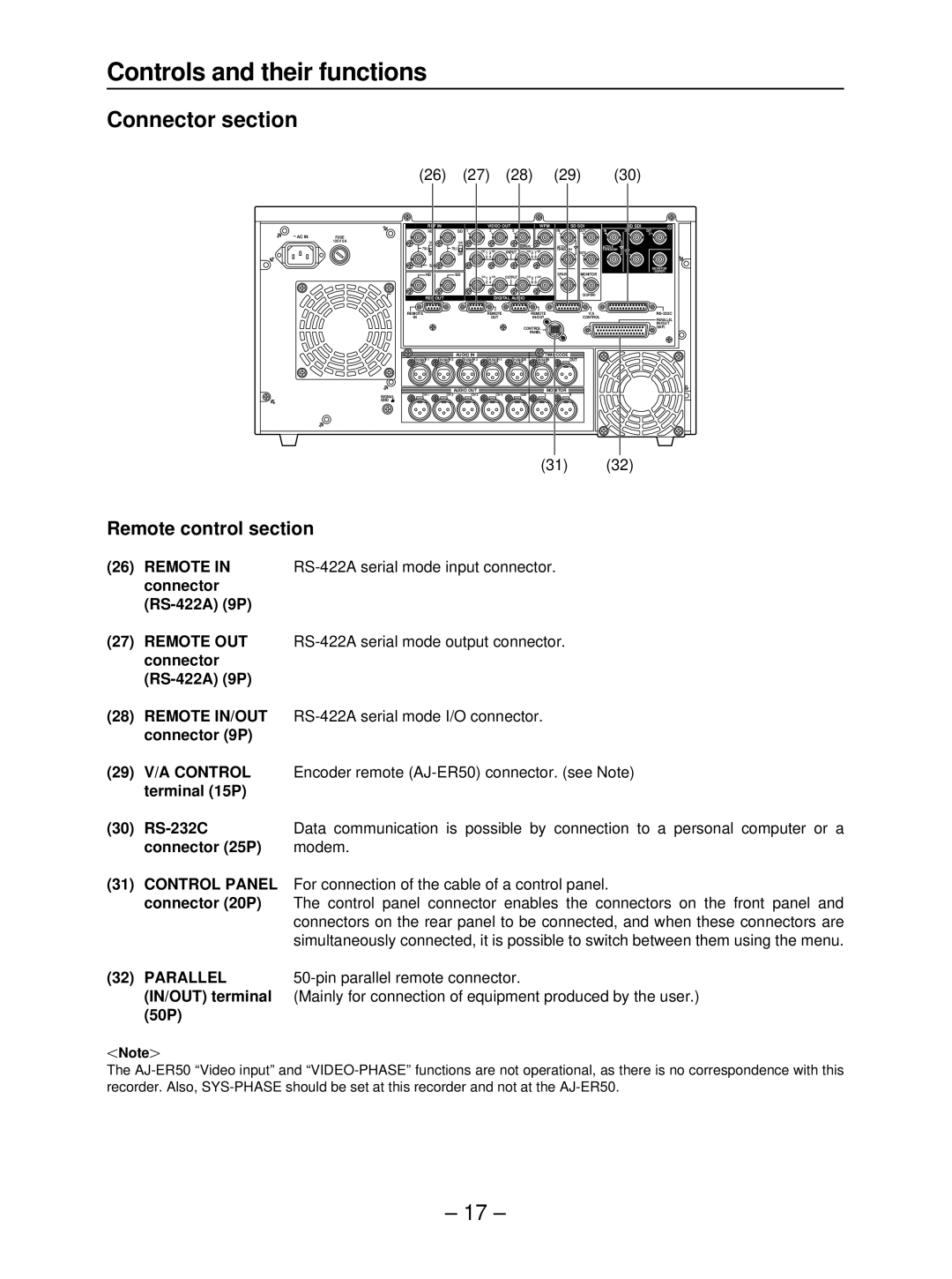
Remote control section
(26) REMOTE IN | |
connector |
|
|
(27)REMOTE OUT
(28)REMOTE IN/OUT
(29)V/A CONTROL Encoder remote
(30) | Data communication is possible by connection to a personal computer or a |
connector (25P) | modem. |
(31)CONTROL PANEL For connection of the cable of a control panel.
connector (20P) The control panel connector enables the connectors on the front panel and
connectors on the rear panel to be connected, and when these connectors are simultaneously connected, it is possible to switch between them using the menu.
(32) PARALLEL | |
(IN/OUT) terminal | (Mainly for connection of equipment produced by the user.) |
(50P) |
|
ONoteN
The
– 17 –
