425 AssemblyInstructions
13/8 X
t/2" LD~/HE'.[15HTNUT
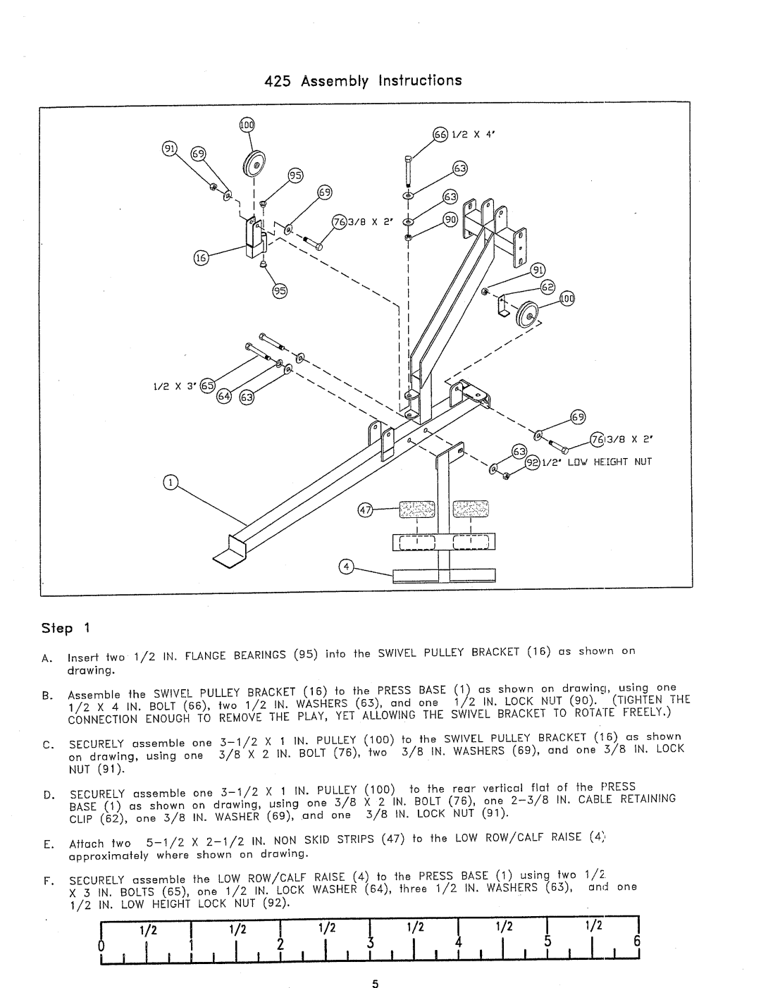
Step 1
A.Insert two 1/2 IN. FLANGEBEARINGS(9.5) into the SWIVEL PULLEY BRACKET(16) os shown drawing.
B.Assemble the SWIVEL PULLEY BRACKET(16) to the PRESS BASE (1) as shown on drowing, using 1/2 X 4 IN. BOLT (66), two 1/2 IN. WASHERS(63), and one 1/2 IN. LOCK NUT (90). (TIGHTEN CONNECTIONENOUGHTO REMO~ETHE PLAY, YET ALLOWING THE SWIVEL BRACKET TO ROTATE FREELY.)
C.SECURELYessemble one
NUT (91).
D. SECURELYessemble | one | X 1 IN. | PULLEY (100) to | the rear vertical | fiat | of | the PRESS | |
BASE (1) as shown | on | drawing, | using | one 3/8 X 2 IN. | BOLT (76), one | IN. | CABLE RETAINING |
CLIP (62), one .3/8 IN. WASHER(69), .and one 3/8 IN. LOCK NUT (91).
E. Attach two
F. SECURELYassemble | the | LOWROW/CALFRAISE (4) | o | the | PRESS BASE (1 | using | two | 1/2. | |||||||
X :5 IN. | BOLTS (65), | one | 1/2 | IN. | LOCK WASHER(64), | three | 1/2 | IN. | WASHERS(65), | end one | |||||
| |||||||||||||||
1/2 IN. | LOWHEIGHT LOCK NUT (92). |
|
|
|
|
|
|
|
|
| |||||
i | i I I I | 1 | l | I | I | 2 I I I I | , | ] | , I | , | ] | I | I | I5 L | I ,,I 6 |
I |
|
|
|
|
|
|
|
|
|
|
|
|
| ||