318 X | 1 | / | / |
| I | / | / |
| / | ||
| I | / | |
| I | / | // |
| // | / |
|
|
|
| |
|
| / |
|
|
| / |
|
112X |
|
|
|
3/8 X 2"
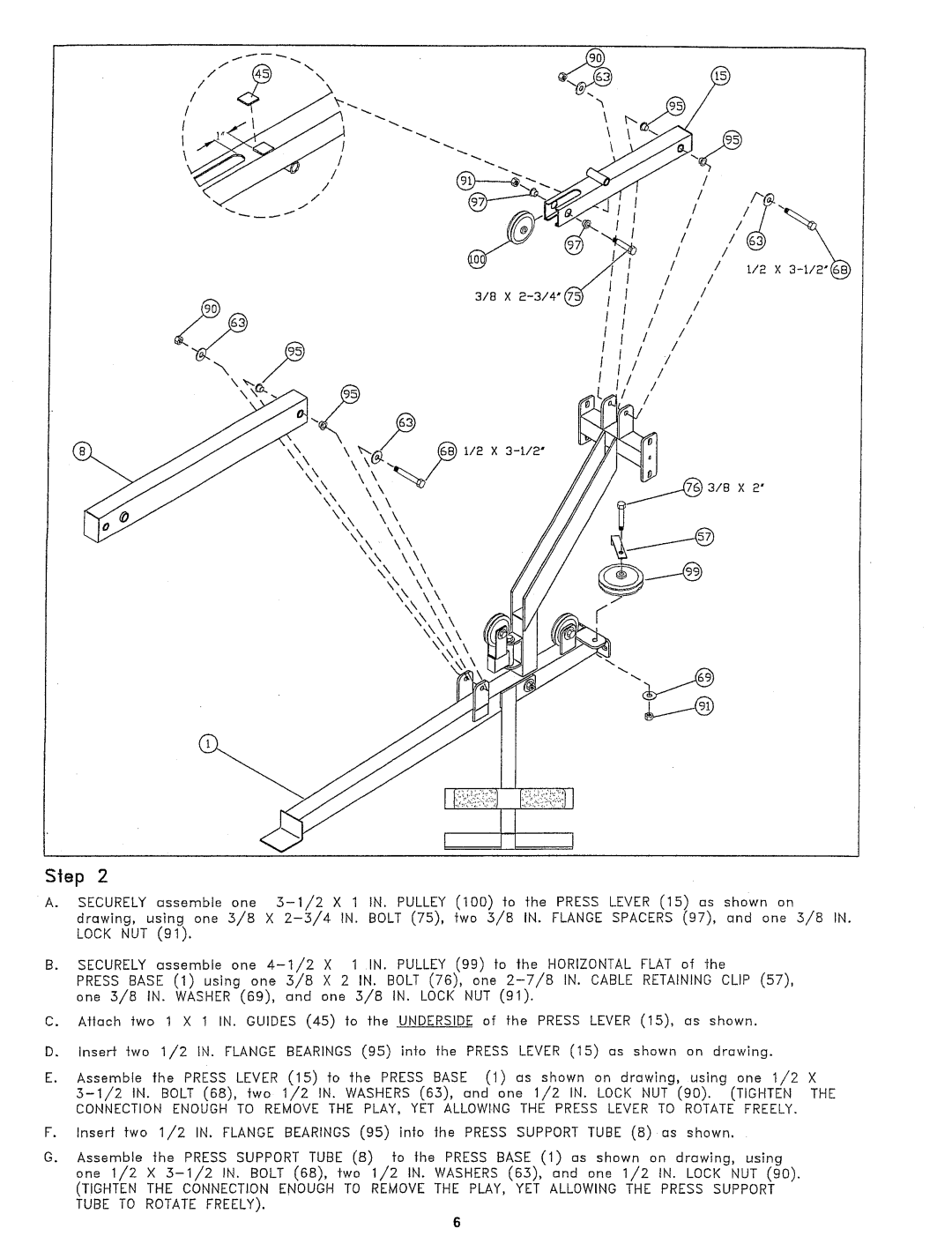
Sep 2
A.SECURELYassemble one
B.SECURELYassemble one
PRESSBASE (1) using one 5/8 X 2 IN. BOLT (76), one
C.Aflach two 1 X 1 IN. GUIDES (45) to fhe UNDERSIDEof fhe PRESSLEVER (15), as shown.
D.Inserf two 1/2 IN. FLANGEBEARINGS(95) into fhe PRESSLEVER (15) as shown on drawing.
E.Assemble the PRESS LEVER (15) to the PRESS BASE (1) us shown on drawing, using one 1/2
F.Inserf fwo 1/2 IN. FLANGEBEARINGS(95) ino the PRESSSUPPORTTUBE (8) as shown.
G.Assemble the PRESS SUPPORTTUBE (8) fo the PRESSBASE (1) as shown on drawing, using one 1/2 X
(TIGHTEN THE CONNECTIONENOUGHTO REMOVETHE PLAY, YET ALLOWING THE PRESS SUPPORT TUBE TO ROTATEFREELY).
6
