S~ep 1
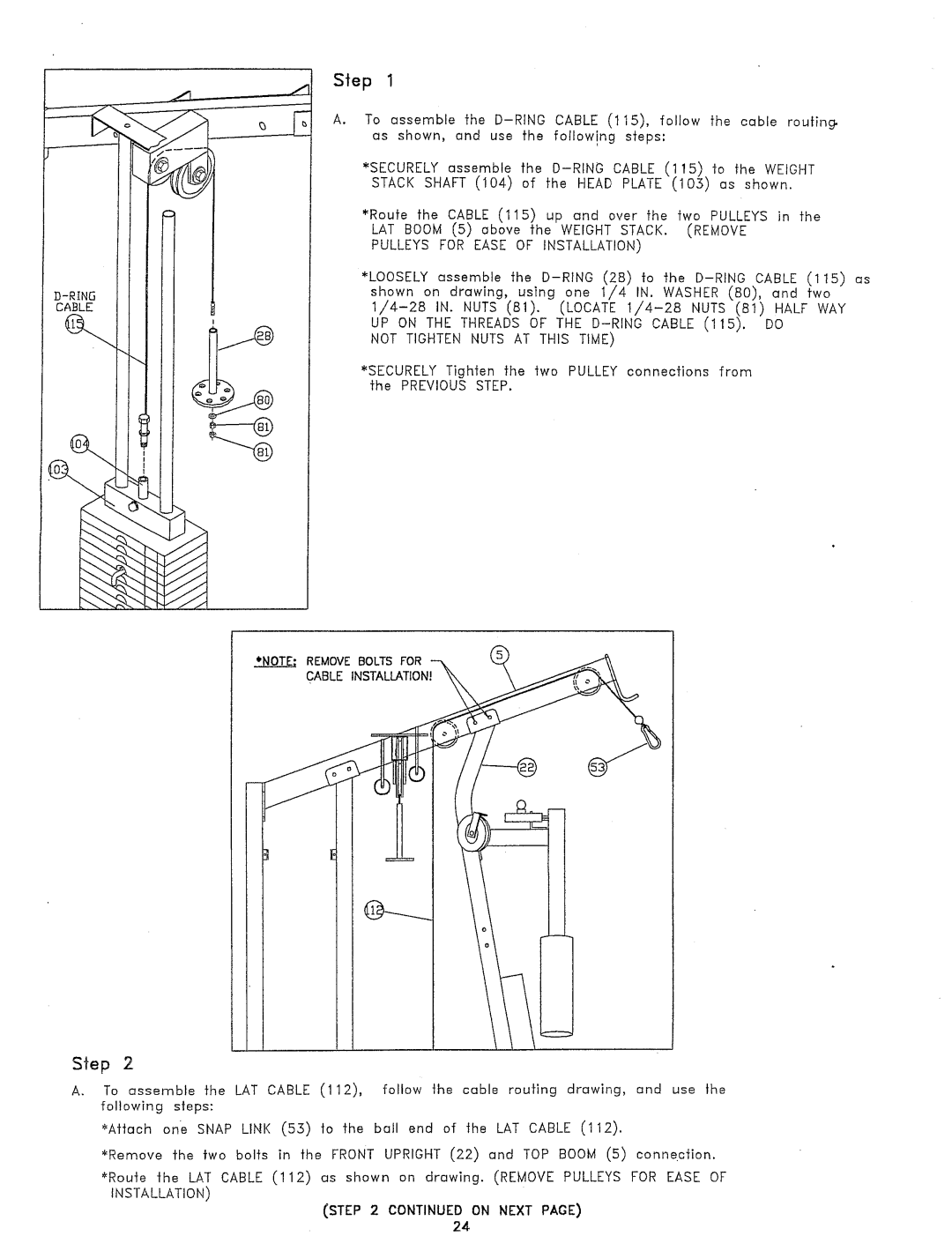
To assemble the
*SECURELYassemble the
*Route the CABLE (115) up cmd over the two PULLEYSin the LAT BOOM(5) aboYe the WEIGHT STACK. (REMOVE PULLEYS FOR EASE OF INSTALLATION)
*LOOSELY assemble the
NOT TIGHTEN NUTS AT THIS TIME)
*SECURELYTighten the two PULLEY connections from the PREVIOUSSTEP.
*NOTE; REMOVEBOLTSFOR CABLEINSTALLATION!
Step 2
A. To assemble the LAT CABLE (112), | follow the | cable routing drawing, and use the | |
following | steps: |
|
|
~Attach | one SNAPLINK (55) to the | bull end of | the LAT CABLE(112). |
~'Remove the two bolts in the FRONTUPRIGHT (22) and TOP BOOM(5) connection.
~Route the LAT CABLE (112) as shown on drawing. (REMOVE PULLEYS FOR EASE INSTALLATION)
(STEP 2 CONTINUEDON NEXT PAGE)
24