o
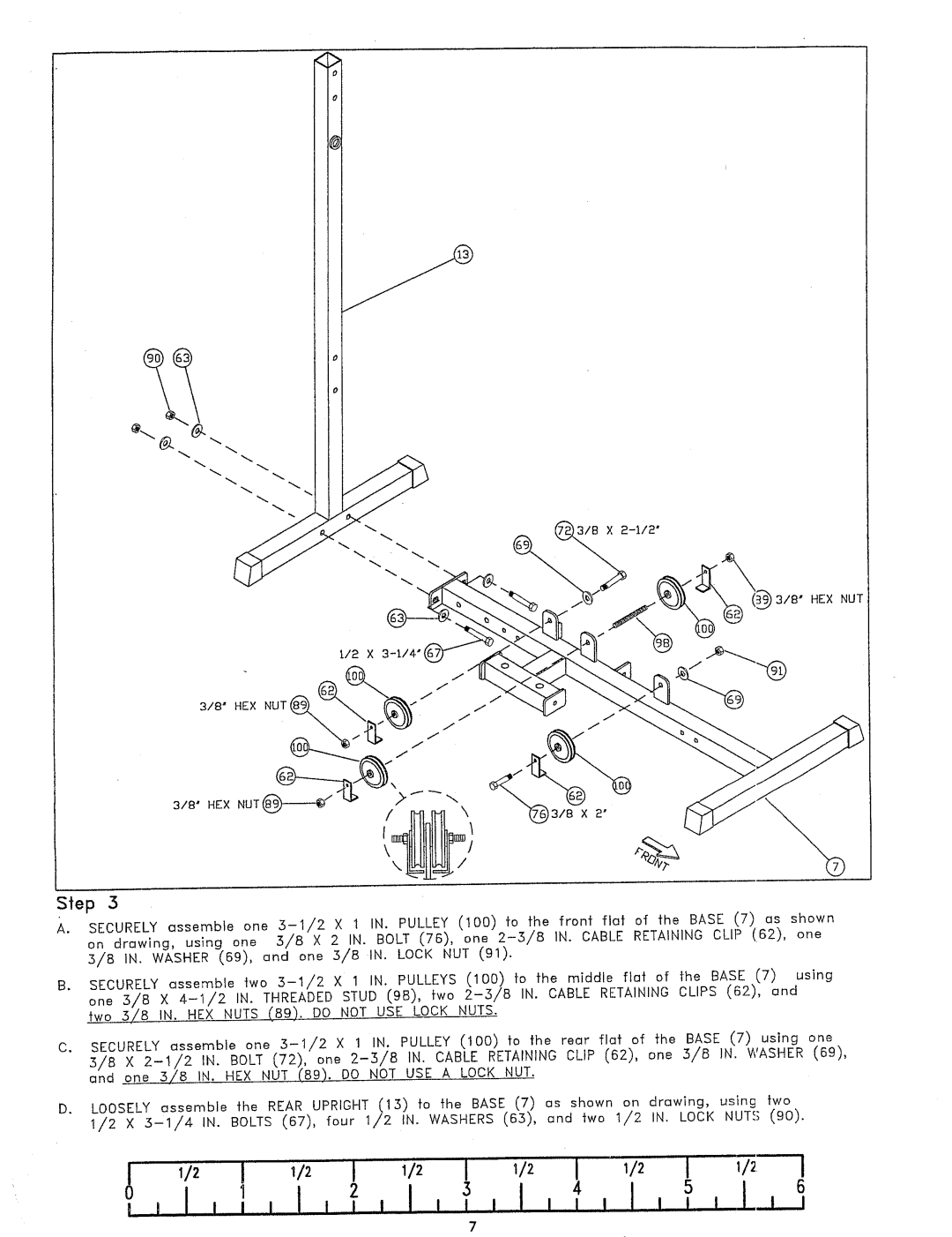
Step 3
A.SECURELYassemble one :5-1/2 × 1 IN. PULLEY(100) fo fhe fr'onf flat of -~he BASE (7) as shown on drawing, using one 3/a × 2 IN. BOLT (76), one 2-3/aIN. CABLE RETAINING CLIP (162), one
5/8 IN. WASHER(69), and one 5/8 IN. LOCK NUT (91).
B.SECURELYassemble two 5-1/2 X 1 IN. PULLEYS (100) fo the middle flat of the BASE (7) using one :5/8 X 4-1/2IN. THREADEDSTUD (9B), two 2-:5/8 IN. CABLE RETAINING CLIPS (62),
two 5/8 IN. HEX NUTS (89). DO NOT USE LOCK NUTS.
C.SECURELYassemble one 3-I/2 X 1 IN. PULLEY (100) to the rear flat of the BASE (7) using
5/B X 2-1/2 IN. BOLT (72), one 2-3/8 IN. CABLE RETAINING CLIP (62), one 3/B IN. WASHER(69), and_one 3/8 IN. HEX NUT (89). DO NOT USE A LOCK NUT.
D.LOOSELYassemble the REAR UPRIGHT (13) to the BASE (7) as shown on drawing, using
1/2 X :5-1/4 IN. BOLTS (67), four 1/2 IN. WASHERS(63), and two 1/2 IN. LOCK NUTS (90).
1/2 I | 'I 1/2 I | I | I | 'i |
I ~ I1 | ~ I I ! I | 4 | 5 | 6 |
| I i i | I L! I |