FIGURE 7 |
I |
G |
I |
17 |
15 1/2 X 3/4” |
BUTTON HEAD |
F |
B |
DONOTTIGHTENYET |
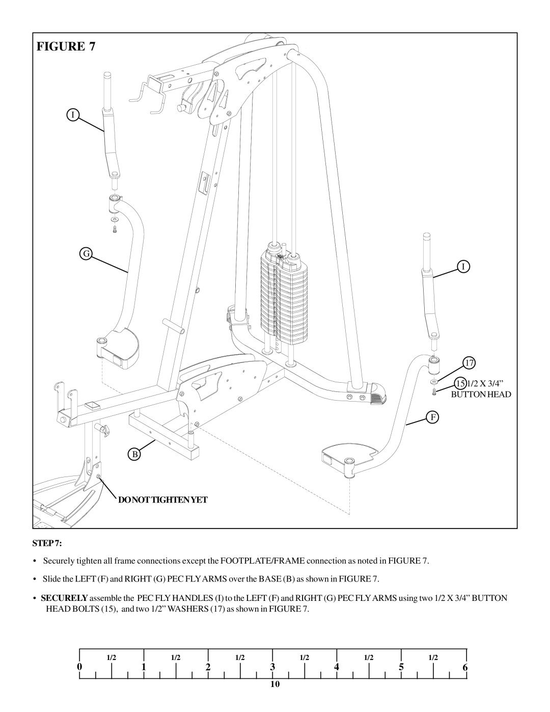
STEP 7:
•Securely tighten all frame connections except the FOOTPLATE/FRAME connection as noted in FIGURE 7.
•Slide the LEFT (F) and RIGHT (G) PEC FLYARMS over the BASE (B) as shown in FIGURE 7.
•SECURELY assemble the PEC FLY HANDLES (I) to the LEFT (F) and RIGHT (G) PEC FLYARMS using two 1/2 X 3/4” BUTTON HEAD BOLTS (15), and two 1/2” WASHERS (17) as shown in FIGURE 7.
| 1/2 |
| 1/2 |
| 1/2 |
| 1/2 |
| 1/2 |
|
| 1/2 |
0 | 1 | 2 | 3 | 4 | 5 | 6 | ||||||
10
