| F |
| 1/2 X 3/4” 15 |
| 3/8 X 4” 5 |
| 19 |
| 18 |
| G |
| O |
| B |
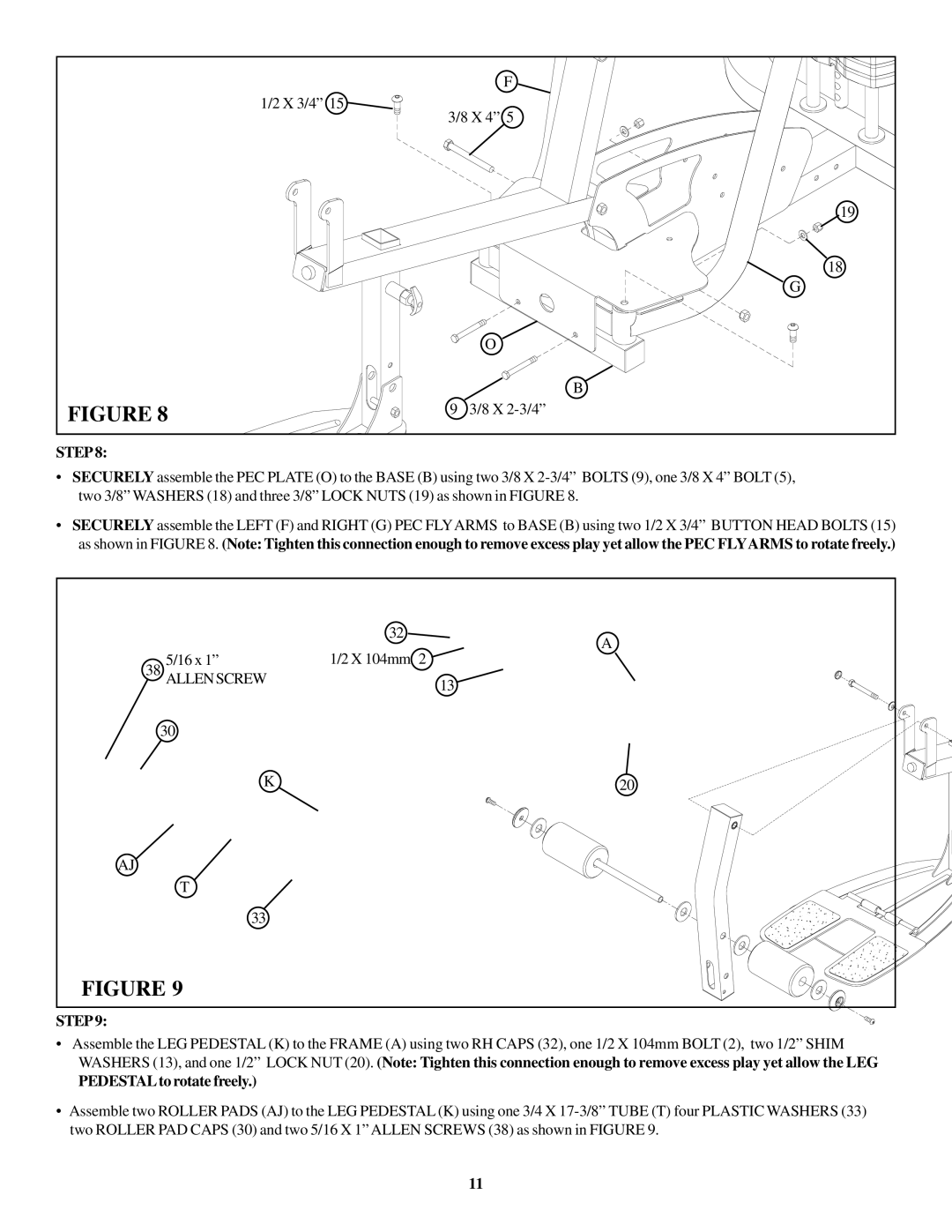
FIGURE 8 | 9 3/8 X |
STEP 8:
•SECURELY assemble the PEC PLATE (O) to the BASE (B) using two 3/8 X
•SECURELY assemble the LEFT (F) and RIGHT (G) PEC FLYARMS to BASE (B) using two 1/2 X 3/4” BUTTON HEAD BOLTS (15) as shown in FIGURE 8. (Note: Tighten this connection enough to remove excess play yet allow the PEC FLYARMS to rotate freely.)
|
| 32 | A |
| 5/16 x 1” | 1/2 X 104mm 2 | |
38 |
| ||
ALLEN SCREW |
| 13 | |
|
|
| |
30 |
|
| |
| K |
| 20 |
AJ |
|
|
|
| T |
|
|
| 33 |
|
|
FIGURE 9 |
|
| |
STEP 9:
•Assemble the LEG PEDESTAL (K) to the FRAME (A) using two RH CAPS (32), one 1/2 X 104mm BOLT (2), two 1/2” SHIM WASHERS (13), and one 1/2” LOCK NUT (20). (Note: Tighten this connection enough to remove excess play yet allow the LEG
PEDESTALto rotate freely.)
•Assemble two ROLLER PADS (AJ) to the LEG PEDESTAL (K) using one 3/4 X
11
