3/8 X 1-3/4” 11
4 3/8 X 5-3/4”
35
19
*Q
G
AP
*NOTE: MAKE SURE “L” CABLE RETAINERS (P)
| AND PULLEY GUARDS (Q) ARE ORIENTATED |
| SO THAT THE CABLE WILL NOT RUB |
FIGURE 18 | WHEN TIGHTENED. |
TOP-VIEW |
STEP 18:
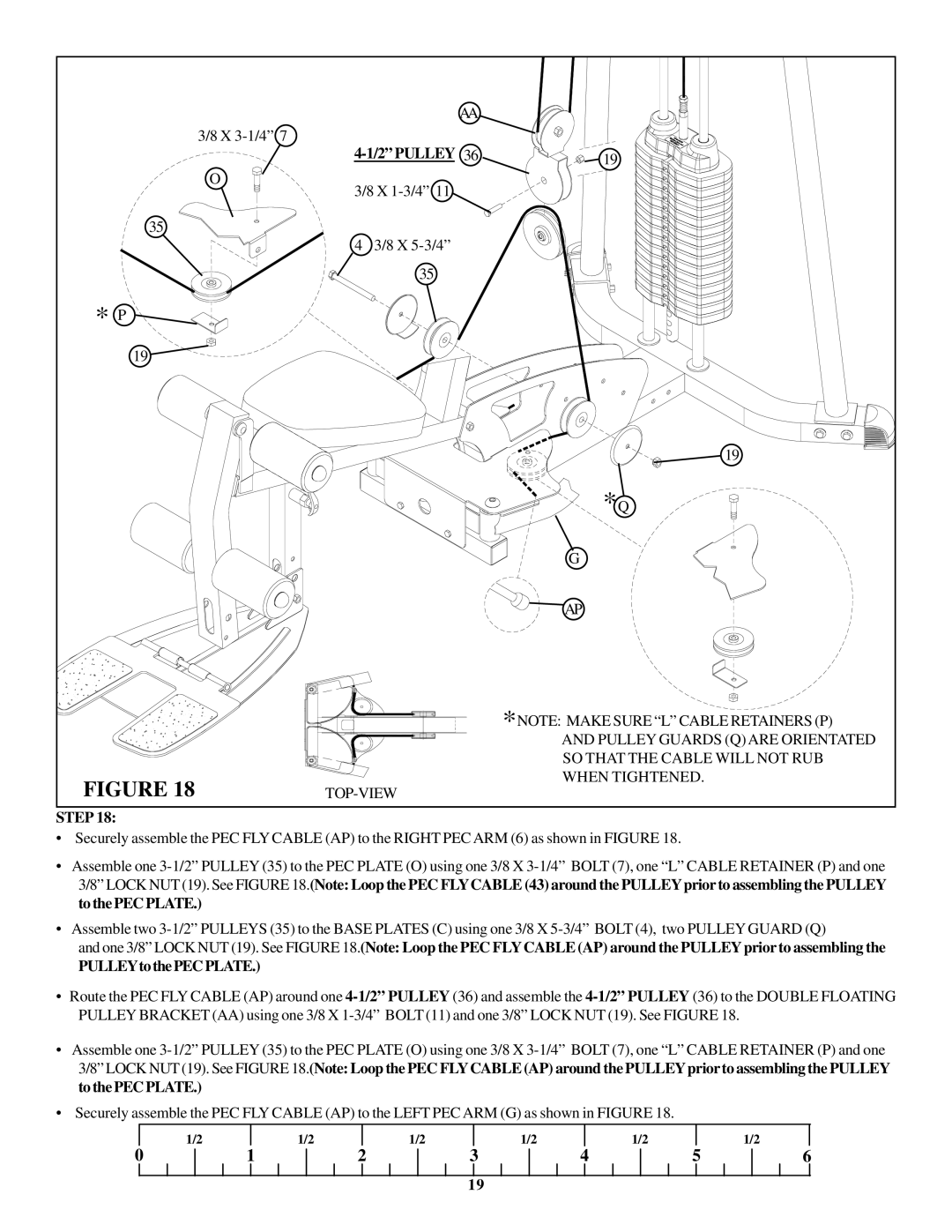
•Securely assemble the PEC FLY CABLE (AP) to the RIGHT PEC ARM (6) as shown in FIGURE 18.
•Assemble one 3-1/2” PULLEY (35) to the PEC PLATE (O) using one 3/8 X 3-1/4” BOLT (7), one “L” CABLE RETAINER (P) and one 3/8” LOCK NUT (19). See FIGURE 18.(Note: Loop the PEC FLYCABLE (43) around the PULLEYpriorto assembling the PULLEY to the PEC PLATE.)
•Assemble two 3-1/2” PULLEYS (35) to the BASE PLATES (C) using one 3/8 X 5-3/4” BOLT (4), two PULLEY GUARD (Q)
and one 3/8” LOCK NUT (19). See FIGURE 18.(Note: Loop the PEC FLYCABLE (AP) around the PULLEYprior to assembling the
PULLEYtothePECPLATE.)
•Route the PEC FLY CABLE (AP) around one 4-1/2” PULLEY (36) and assemble the 4-1/2” PULLEY (36) to the DOUBLE FLOATING PULLEY BRACKET (AA) using one 3/8 X 1-3/4” BOLT (11) and one 3/8” LOCK NUT (19). See FIGURE 18.
•Assemble one 3-1/2” PULLEY (35) to the PEC PLATE (O) using one 3/8 X 3-1/4” BOLT (7), one “L” CABLE RETAINER (P) and one 3/8” LOCK NUT (19). See FIGURE 18.(Note: Loop the PEC FLYCABLE (AP) around the PULLEYpriorto assembling the PULLEY to the PEC PLATE.)
•Securely assemble the PEC FLY CABLE (AP) to the LEFT PEC ARM (G) as shown in FIGURE 18.
| 1/2 | | 1/2 | | 1/2 | | 1/2 | | 1/2 | | | 1/2 |
0 | 1 | 2 | 3 | 4 | 5 | 6 |
19

