1752 and 1754 SHDSL Router User’s Guide
Chapter 2 – Hardware Setup and Startup
Front Panel LED and Rear Panel description
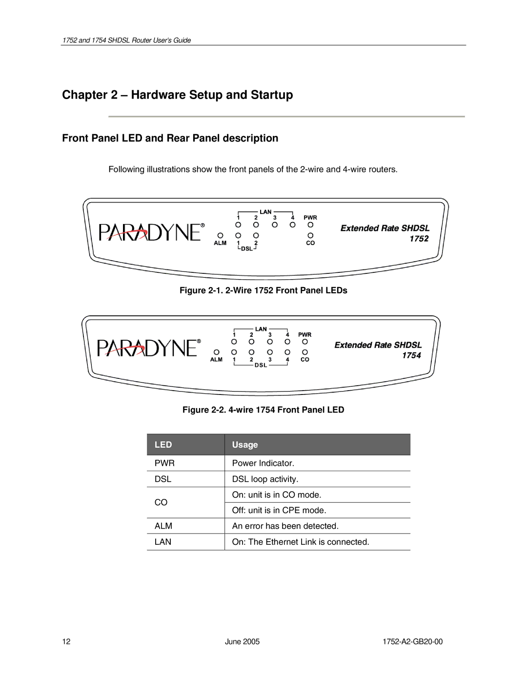
Following illustrations show the front panels of the
Figure 2-1. 2-Wire 1752 Front Panel LEDs
Figure 2-2. 4-wire 1754 Front Panel LED
LED
PWR
DSL
CO
ALM
LAN
Usage
Power Indicator.
DSL loop activity.
On: unit is in CO mode.
Off: unit is in CPE mode.
An error has been detected.
On: The Ethernet Link is connected.
12 | June 2005 |