1752 and 1754 SHDSL Router User’s Guide
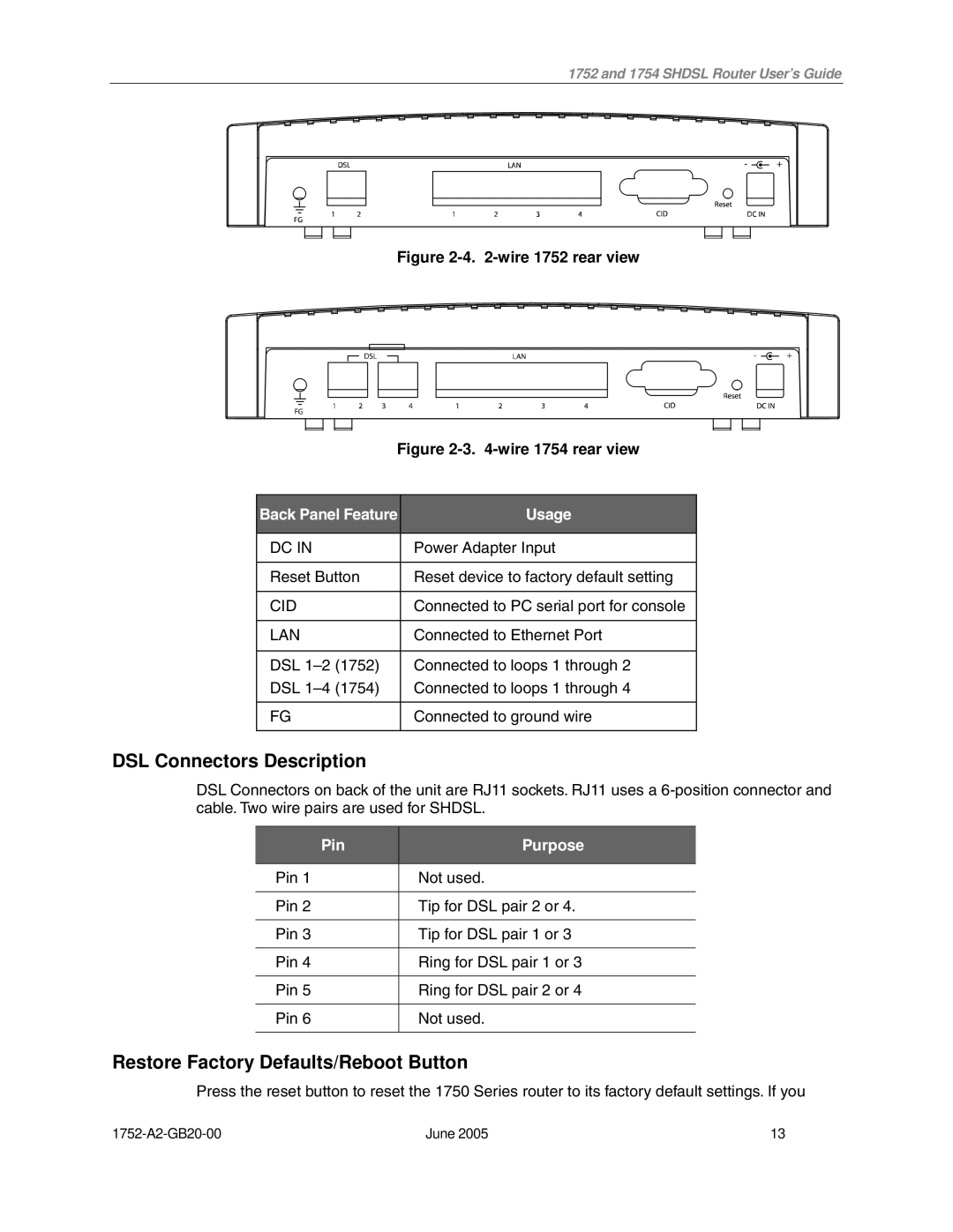
Figure 2-4. 2-wire 1752 rear view
Figure 2-3. 4-wire 1754 rear view
Back Panel Feature | Usage |
|
|
DC IN | Power Adapter Input |
|
|
Reset Button | Reset device to factory default setting |
|
|
CID | Connected to PC serial port for console |
|
|
LAN | Connected to Ethernet Port |
|
|
DSL | Connected to loops 1 through 2 |
DSL | Connected to loops 1 through 4 |
|
|
FG | Connected to ground wire |
|
|
DSL Connectors Description
DSL Connectors on back of the unit are RJ11 sockets. RJ11 uses a
Pin | Purpose |
|
|
Pin 1 | Not used. |
|
|
Pin 2 | Tip for DSL pair 2 or 4. |
|
|
Pin 3 | Tip for DSL pair 1 or 3 |
|
|
Pin 4 | Ring for DSL pair 1 or 3 |
|
|
Pin 5 | Ring for DSL pair 2 or 4 |
|
|
Pin 6 | Not used. |
|
|
Restore Factory Defaults/Reboot Button
Press the reset button to reset the 1750 Series router to its factory default settings. If you
June 2005 | 13 |