2710 specifications
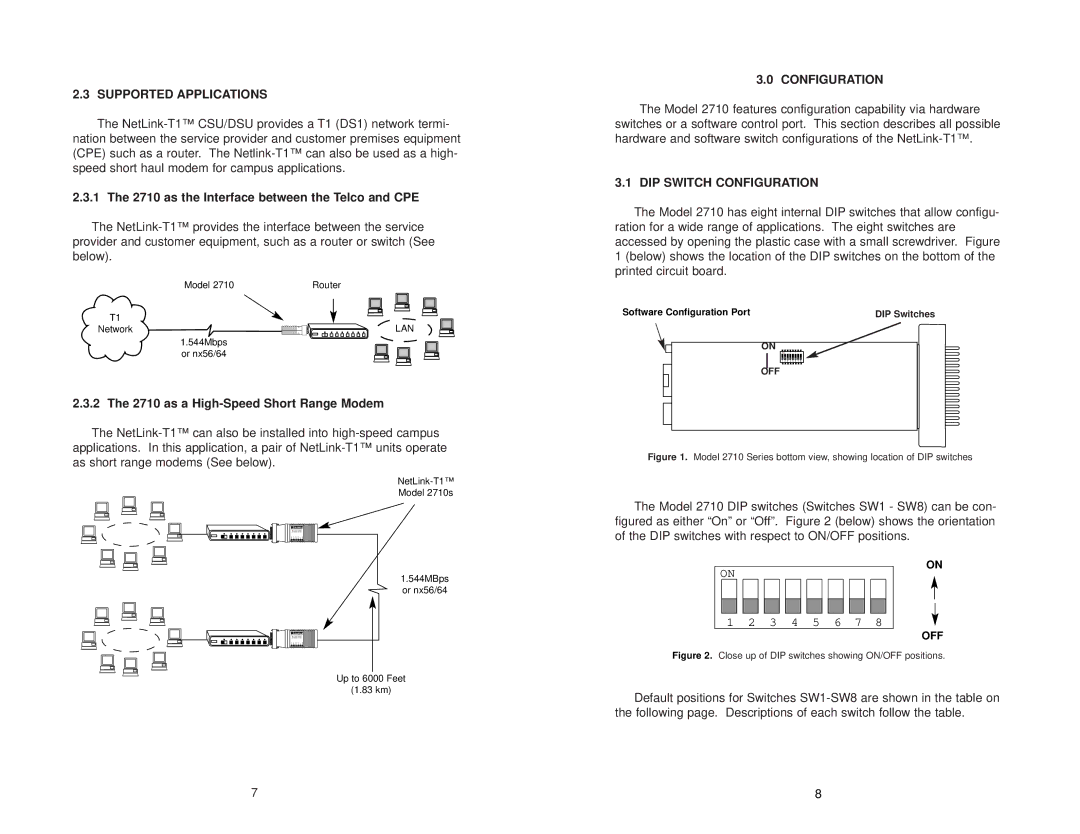
The Patton Electronic 2710 is a versatile IoT (Internet of Things) device that has garnered attention for its robust capabilities in facilitating reliable communication and seamless data transmission. Tailored for various industrial applications, this product stands out with its blend of cutting-edge technologies and practical features, making it an essential tool for businesses looking to enhance their connectivity infrastructure.One of the main features of the Patton 2710 is its multi-interface support. This device is equipped with a variety of ports, including serial interfaces like RS-232, RS-485, and RS-422, as well as Ethernet and USB connectivity options. This versatility allows it to connect seamlessly with different devices and systems, from legacy equipment to modern networked devices, enabling efficient data exchange and communication across a variety of protocols.
The Patton 2710 also boasts robust protocol support, including various telecommunications and networking protocols such as TCP/IP, UDP, and SNMP. This extensive compatibility ensures that it can operate effectively in diverse environments, whether in a factory setting monitoring machinery or in a smart city application controlling infrastructure systems. With its support for these protocols, users can implement advanced monitoring and management solutions, improving operational efficiency and reducing downtime.
In terms of technology, the Patton 2710 features advanced security measures that safeguard the integrity of the data being transmitted. With built-in encryption and secure communication protocols, users can rest assured that their sensitive information remains protected against potential cyber threats. This is increasingly important in today's digitally interconnected landscape, where data breaches can have serious repercussions.
The device is also designed for ease of use and installation. Its intuitive web-based management interface simplifies configuration and monitoring, allowing users to set up the device quickly without extensive technical knowledge. This user-friendly design empowers organizations to implement the device across their operations with minimal training and support.
Another significant characteristic of the Patton 2710 is its rugged build quality. Designed to withstand harsh industrial environments, the device is often housed in enclosures that protect it from dust, moisture, and extreme temperatures. This durability ensures that it can operate reliably in demanding conditions, making it suitable for a wide range of industries, from manufacturing to transportation.
In summary, the Patton Electronic 2710 stands out as a powerful tool for enhancing connectivity and facilitating IoT applications. With its multi-interface capabilities, robust protocol support, advanced security features, user-friendly design, and rugged build, it provides businesses with the reliable solutions they need to thrive in an increasingly connected world.

