Model 2977 DialFire RAS User Guide | 3 • Installing the Model 2977 adapter |
|
|
6.Write down the serial number of the adapter in the space provided below. The serial number label has the general form: “S/N (S) XXX XXXXX”
Serial Number: ________________________
7.Insert the adapter into the slot and screw the endplate to the computer chassis.
8.Replace the computer’s cover.
9.Connect the PRI line(s) to the adapter. If the adapter is a RAS PE1, only Line 1 (see figure 5 on page 34) is active. If the adapter is a RAS PE2, two PRI lines are supported and both connectors may be used.
Adapter installation is complete. Refer to Chapter 4, “Driver installation and configuration”.
Model 2977 PT1 PT2 adapter installation
The DialFire RAS PTE Series adapters provide one or two 30B+D PRI interfaces in a package that fits in a sin- gle PCI slot in your server.
Because it uses DSP (digital signal processor) technology, the DialFire RAS adapter supports digital or analog connections on PRI circuits. The adapter supports up to 30 channels on each line.
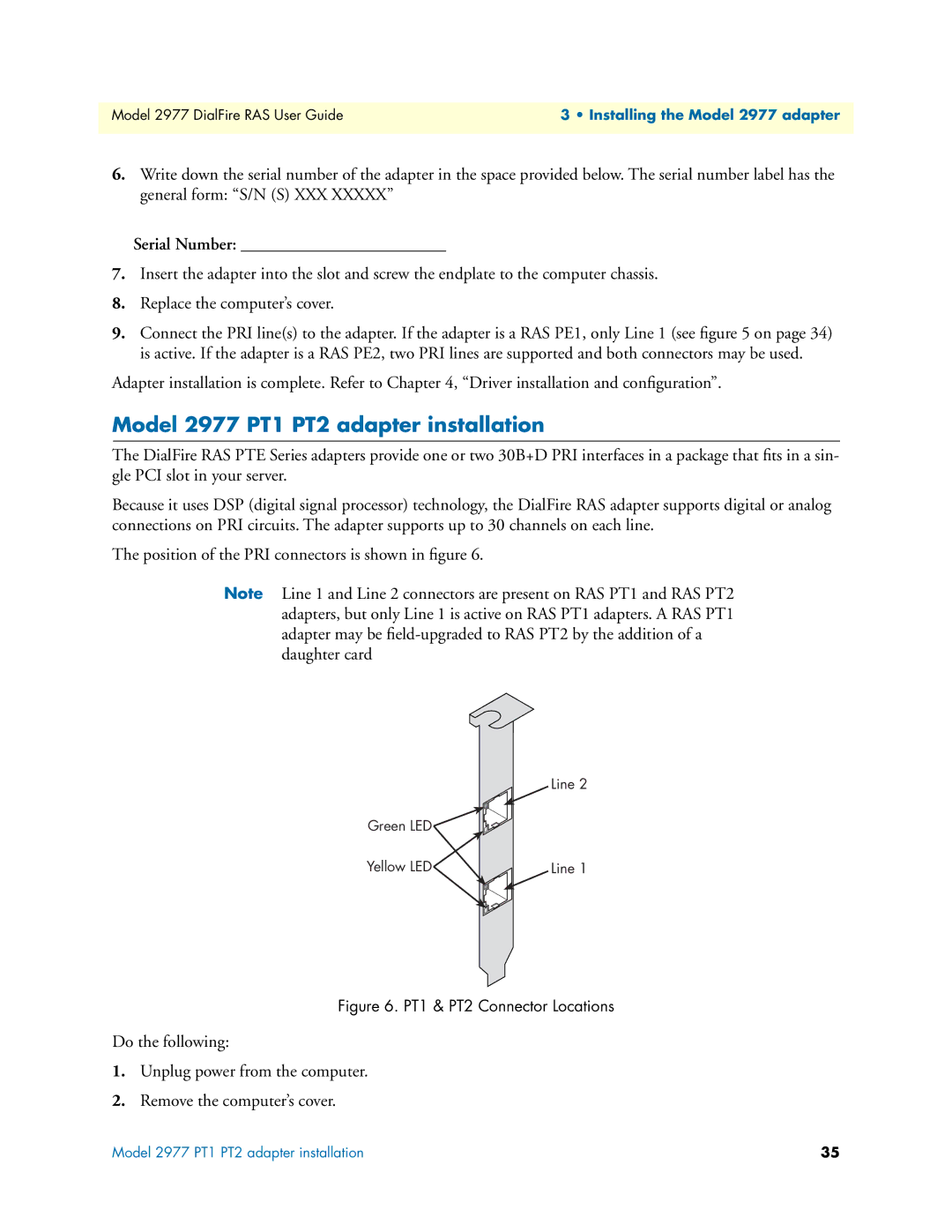
The position of the PRI connectors is shown in figure 6.
Note Line 1 and Line 2 connectors are present on RAS PT1 and RAS PT2 adapters, but only Line 1 is active on RAS PT1 adapters. A RAS PT1 adapter may be
Line 2
Green LED![]()
![]()
Yellow LED | Line 1 |
Figure 6. PT1 & PT2 Connector Locations
Do the following:
1.Unplug power from the computer.
2.Remove the computer’s cover.
Model 2977 PT1 PT2 adapter installation | 35 |