3 • Installing the Model 2977 adapter | Model 2977 DialFire RAS User Guide |
|
|
Model 2977 PE1 PE2 adapter installation
The DialFire RAS PTE Series adapters provide one or two 30B+D PRI interfaces in a package that fits in a sin- gle PCI slot in your server.
Because it uses DSP (digital signal processor) technology, the DialFire RAS adapter supports digital or analog connections on PRI circuits. The adapter supports up to 30 channels on each line.
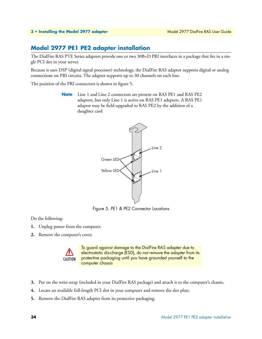
The position of the PRI connectors is shown in figure 5.
Note Line 1 and Line 2 connectors are present on RAS PE1 and RAS PE2 adapters, but only Line 1 is active on RAS PE1 adapters. A RAS PE1 adapter may be
Line 2
Green LED![]()
![]()
Yellow LED | Line 1 |
Figure 5. PE1 & PE2 Connector Locations
Do the following:
1.Unplug power from the computer.
2.Remove the computer’s cover.
To guard against damage to the DialFire RAS adapter due to electrostatic
3.Put on the wrist strap (included in your DialFire RAS package) and attach it to the computer’s chassis.
4.Locate an available
5.Remove the DialFire RAS adapter from its protective packaging.
34 | Model 2977 PE1 PE2 adapter installation |