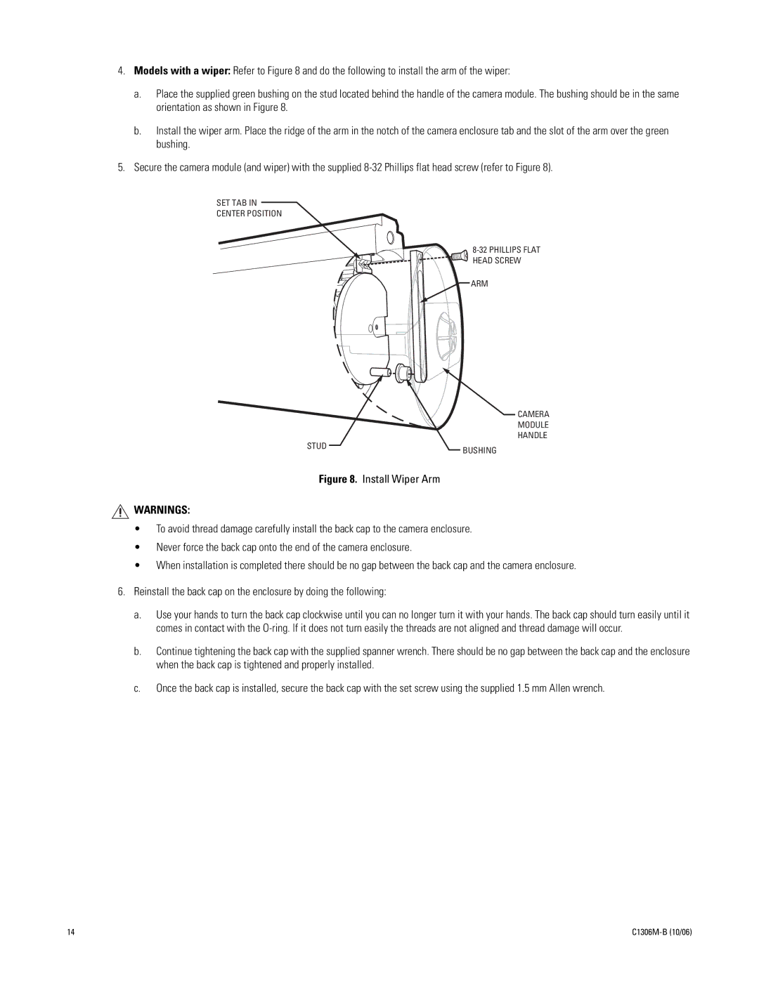
4.Models with a wiper: Refer to Figure 8 and do the following to install the arm of the wiper:
a.Place the supplied green bushing on the stud located behind the handle of the camera module. The bushing should be in the same orientation as shown in Figure 8.
b.Install the wiper arm. Place the ridge of the arm in the notch of the camera enclosure tab and the slot of the arm over the green bushing.
5.Secure the camera module (and wiper) with the supplied
SET TAB IN
CENTER POSITION
ARM
CAMERA
MODULE
HANDLE
STUD | BUSHING |
|
Figure 8. Install Wiper Arm
WARNINGS:
•To avoid thread damage carefully install the back cap to the camera enclosure.
•Never force the back cap onto the end of the camera enclosure.
•When installation is completed there should be no gap between the back cap and the camera enclosure.
6.Reinstall the back cap on the enclosure by doing the following:
a.Use your hands to turn the back cap clockwise until you can no longer turn it with your hands. The back cap should turn easily until it comes in contact with the
b.Continue tightening the back cap with the supplied spanner wrench. There should be no gap between the back cap and the enclosure when the back cap is tightened and properly installed.
c.Once the back cap is installed, secure the back cap with the set screw using the supplied 1.5 mm Allen wrench.
14 |
