Set the Tilt Angle of the Camera Module
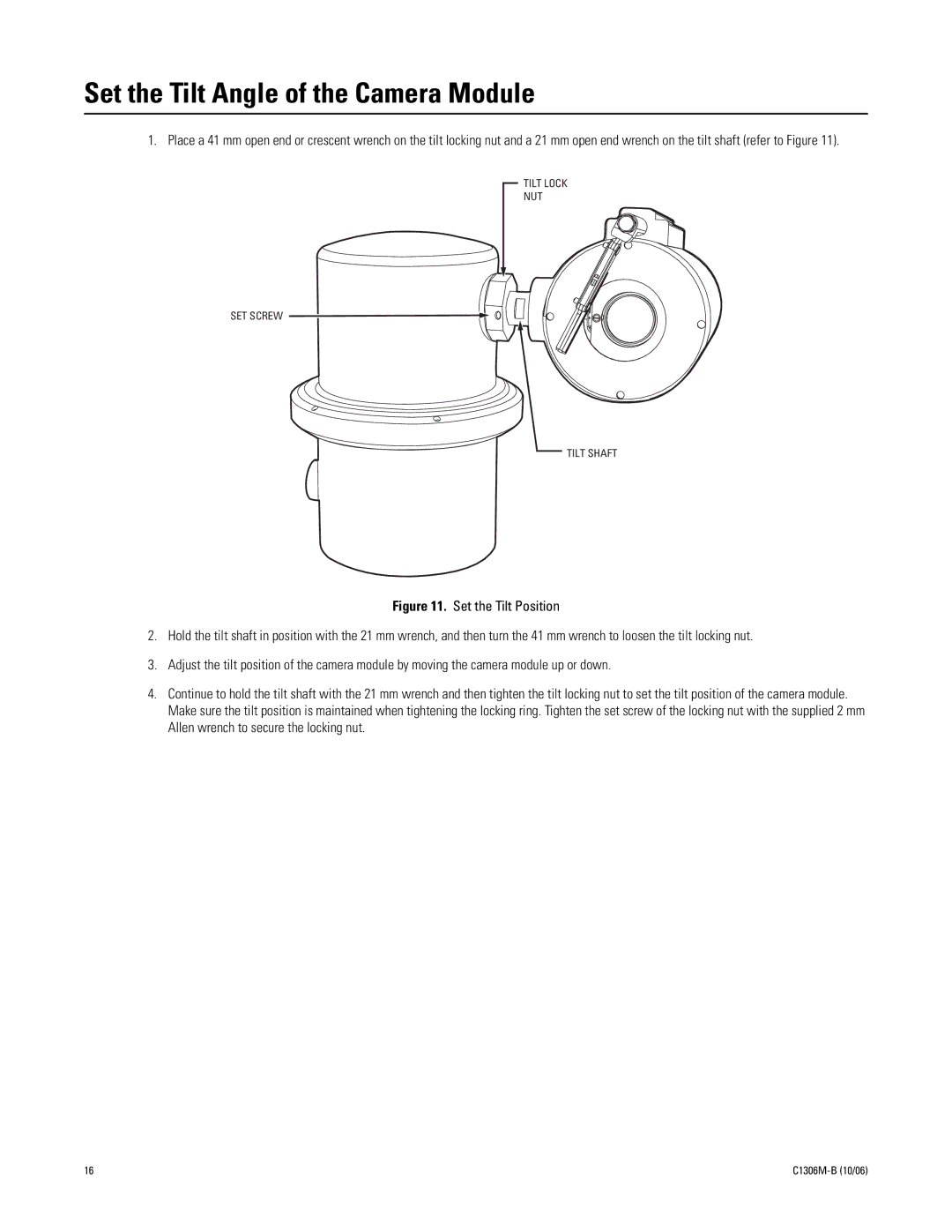
1. Place a 41 mm open end or crescent wrench on the tilt locking nut and a 21 mm open end wrench on the tilt shaft (refer to Figure 11).
TILT LOCK
NUT
SET SCREW
TILT SHAFT
Figure 11. Set the Tilt Position
2.Hold the tilt shaft in position with the 21 mm wrench, and then turn the 41 mm wrench to loosen the tilt locking nut.
3.Adjust the tilt position of the camera module by moving the camera module up or down.
4.Continue to hold the tilt shaft with the 21 mm wrench and then tighten the tilt locking nut to set the tilt position of the camera module. Make sure the tilt position is maintained when tightening the locking ring. Tighten the set screw of the locking nut with the supplied 2 mm Allen wrench to secure the locking nut.
16 |