SPECTRA LITE™ PENDANT COMPONENTS
Black
Same as
Smoked lower dome (1/2
Chrome lower dome (2
Same as
SPECTRA LITE™ IN-CEILING COMPONENTS
INSTALLATION FOR IN-CEILING MODELS
To install the dome proceed through the steps in this section, beginning with the Ceiling and Back Box Preparation section.
CEILING AND BACK BOX PREPARATION
NOTE: Use the SCA1 (structural ceiling adapter) if additional support is required.
CAUTION: Be careful not to cut
outside of the line.
If you do, you may not be able to install the back box. Also, the trim ring may not cover the hole.
HARD CEILING
1.Locate the center point where you want to drill a hole in the ceiling. (The ceiling tile cannot be thinner than 0.50 inch [1.27 cm] nor thicker than 1.75 inches [4.45 cm].)
2.Drill a hole in the ceiling using a
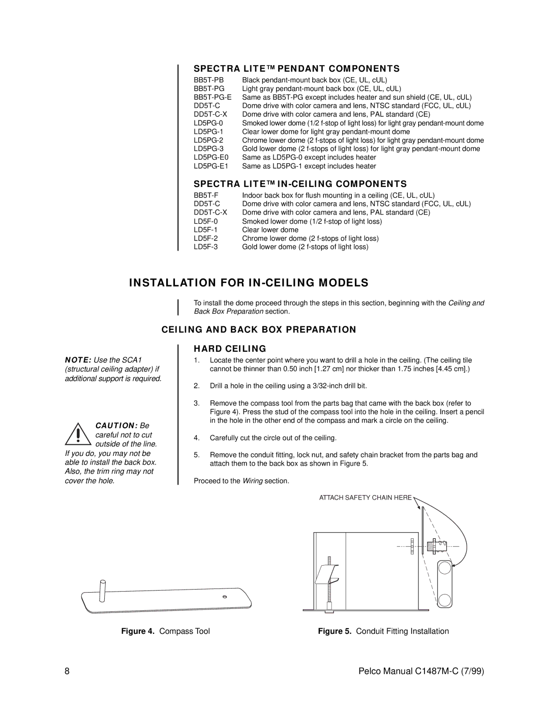
3.Remove the compass tool from the parts bag that came with the back box (refer to Figure 4). Press the stud of the compass tool into the hole in the ceiling. Insert a pencil in the hole in the other end of the compass and mark a circle on the ceiling.
4.Carefully cut the circle out of the ceiling.
5.Remove the conduit fitting, lock nut, and safety chain bracket from the parts bag and attach them to the back box as shown in Figure 5.
Proceed to the Wiring section.
ATTACH SAFETY CHAIN HERE
Figure 4. Compass Tool | Figure 5. Conduit Fitting Installation |
8 | Pelco Manual |