KBD300A KEYBOARD
1.Use the RJ-45 straight data cable that comes with the KBD300A to connect the keyboard to the RJ-45 wall block, provided in the KBDKIT.
2.Connect the power supply (provided in the KBDKIT) to terminals 3 and 4 on the wall block. Polarity is unimportant.
3.Complete the connection as described for the appropriate communication mode:
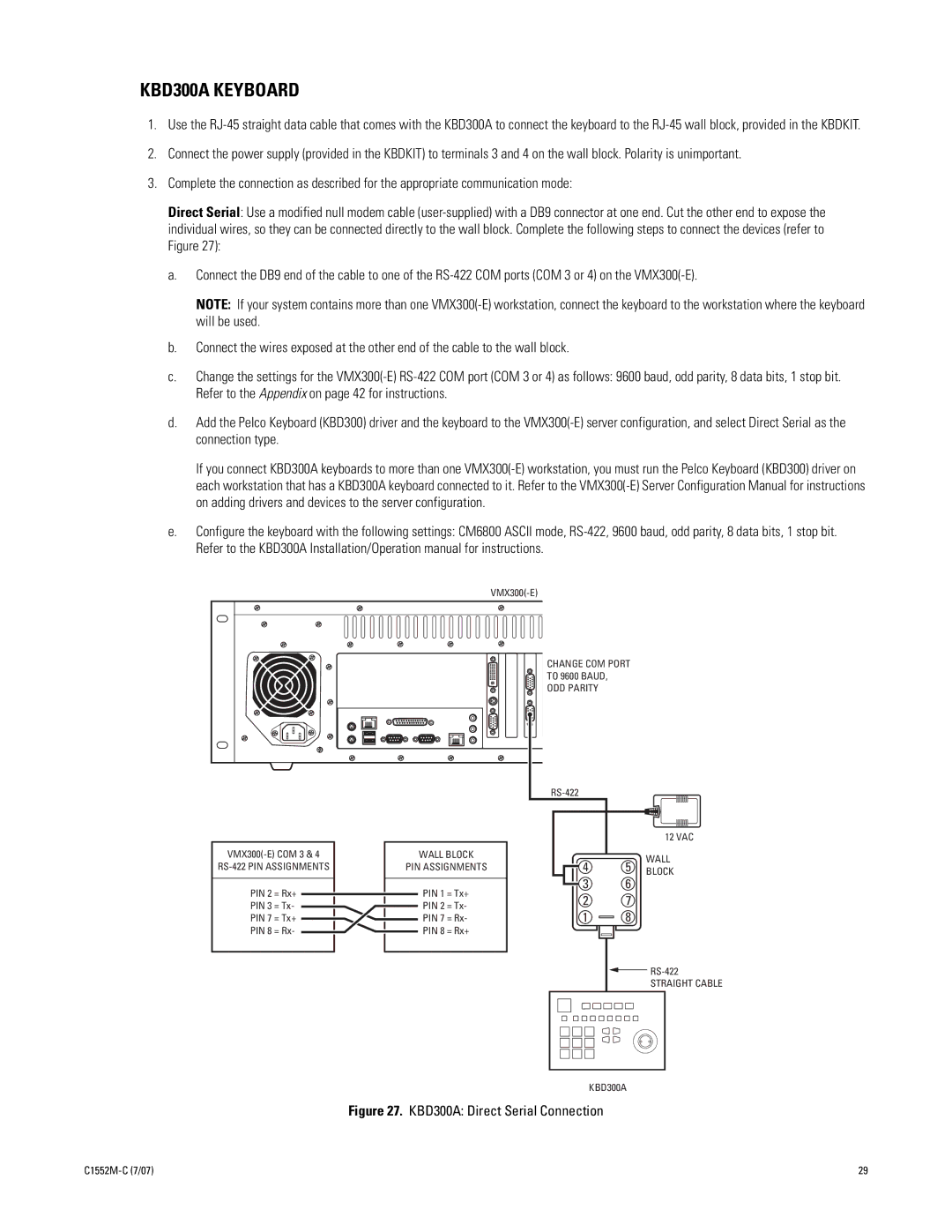
Direct Serial: Use a modified null modem cable (user-supplied) with a DB9 connector at one end. Cut the other end to expose the individual wires, so they can be connected directly to the wall block. Complete the following steps to connect the devices (refer to Figure 27):
a.Connect the DB9 end of the cable to one of the RS-422 COM ports (COM 3 or 4) on the VMX300(-E).
NOTE: If your system contains more than one VMX300(-E) workstation, connect the keyboard to the workstation where the keyboard will be used.
b.Connect the wires exposed at the other end of the cable to the wall block.
c.Change the settings for the VMX300(-E) RS-422 COM port (COM 3 or 4) as follows: 9600 baud, odd parity, 8 data bits, 1 stop bit. Refer to the Appendix on page 42 for instructions.
d.Add the Pelco Keyboard (KBD300) driver and the keyboard to the VMX300(-E) server configuration, and select Direct Serial as the connection type.
If you connect KBD300A keyboards to more than one VMX300(-E) workstation, you must run the Pelco Keyboard (KBD300) driver on each workstation that has a KBD300A keyboard connected to it. Refer to the VMX300(-E) Server Configuration Manual for instructions on adding drivers and devices to the server configuration.
e.Configure the keyboard with the following settings: CM6800 ASCII mode, RS-422, 9600 baud, odd parity, 8 data bits, 1 stop bit. Refer to the KBD300A Installation/Operation manual for instructions.
VMX300(-E)
CHANGE COM PORT
 TO 9600 BAUD,
ODD PARITY
| | | | | | | 12 VAC |
| VMX300(-E) COM 3 & 4 | WALL BLOCK | 4 | 5 | WALL |
| RS-422 PIN ASSIGNMENTS | PIN ASSIGNMENTS |
| BLOCK |
| PIN 2 | = Rx+ | PIN 1 | = Tx+ | 3 | 6 | |
| 2 | 7 | |
| PIN 3 | = Tx- | PIN 2 | = Tx- | |
| 1 | 8 | |
| PIN 7 | = Tx+ | PIN 7 | = Rx- | |
| PIN 8 | = Rx- | PIN 8 | = Rx+ | | | |
| | | | | | | RS-422 |
| | | | | | | STRAIGHT CABLE |
KBD300A
Figure 27. KBD300A: Direct Serial Connection

![]() TO 9600 BAUD,
TO 9600 BAUD,