SERIAL OUTPUT DEVICE
Connect a serial output device to the
After installing system hardware, complete the following configuration steps:
1.Add the Serial Output driver and the serial output device to the
2.Change the serial output device settings to match the
IP-BASED DEVICES
You can connect the following devices to the
•DX8000 and DX9000 Series DVRs
•PelcoNet MPEG Series transmission systems (NET300 Series, NET350 Series, NET4001A)
•NVR300 Series network video recorders
•Matrix switchers (through a PelcoNet transmission system)
•Spectra/Esprit camera positioning systems (through a PelcoNet transmission system)
•
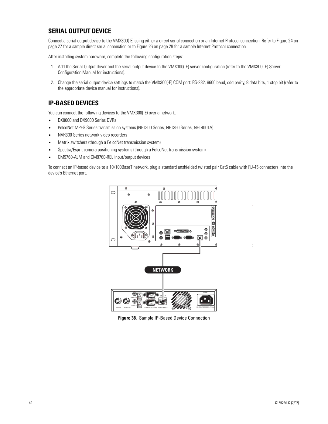
To connect an
|
| NETWORK |
| |
|
|
|
| Power |
|
|
| Ethernet |
|
|
| Audio Out |
|
|
|
| COM2: RS232 |
|
|
|
| Audio In |
|
|
Video In | Video Out | COM1: RS232/485 | 10/100 | |
Figure 38. Sample IP-Based Device Connection
40 |