CM9700 MATRIX SWITCHING SYSTEMS
The following connection instructions apply to CM9700 matrix systems that use CC1 software version 9.xx or higher and that use the Pelco P driver in the VMX300(-E) server configuration (note that “CM9700”includes the CM9740, CM9760, CM9770, and CM9780 matrix systems).
NOTE: If you are using CC1 software version 8.03.012 or lower, the parameters of the CM9760-MGR software allow some variations in the COM port connections and settings. Refer to Alternate CM9700 Connection on page 37 for an alternate connection option, and refer to the VMX300-E Server Configuration Manual for information on the CM9760-MGR parameters.
1.Use a modified null modem cable (user-supplied) with a DB9 connector at one end. Cut the other end to expose the individual wires, so that they can be connected directly to the wall block.
2.Connect the DB9 end of the cable to one of the RS-422 COM ports (COM 3 or 4) on the VMX300(-E).
3.Connect the wires exposed at the other end of the cable to the wall block.
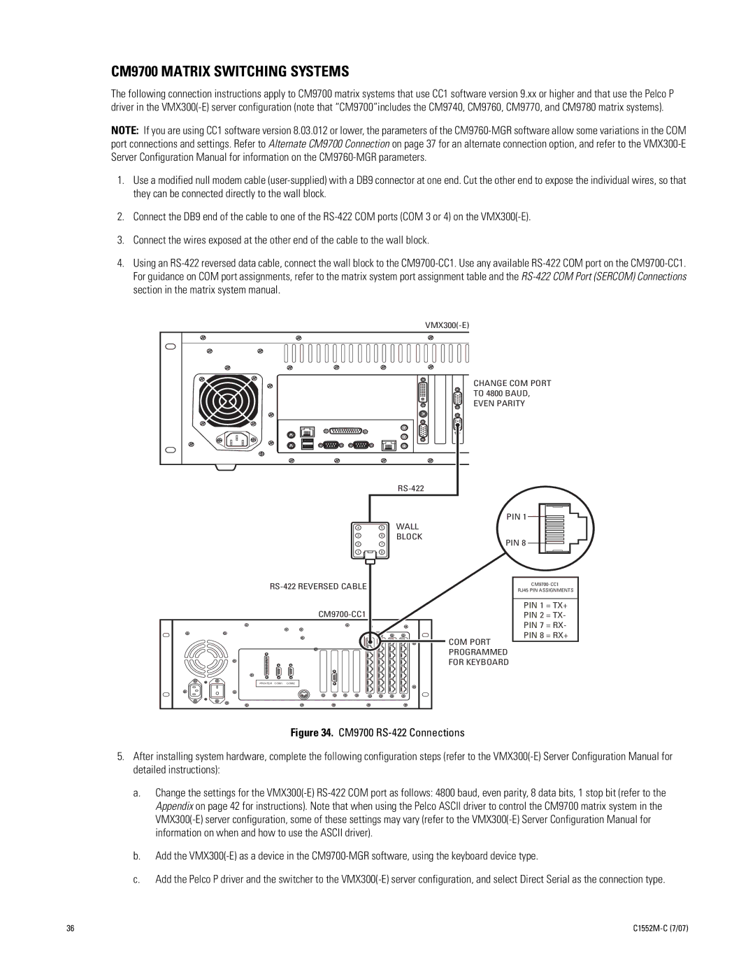
4.Using an RS-422 reversed data cable, connect the wall block to the CM9700-CC1. Use any available RS-422 COM port on the CM9700-CC1. For guidance on COM port assignments, refer to the matrix system port assignment table and the RS-422 COM Port (SERCOM) Connections section in the matrix system manual.
VMX300(-E)
CHANGE COM PORT
 TO 4800 BAUD,
EVEN PARITY
4
3
2
1
RS-422 REVERSED CABLE
CM9700-CC1
PIN 1 

WALL
BLOCK PIN 8
PIN 8 

CM9700-CC1
RJ45 PIN ASSIGNMENTS
PIN 1 = TX+
PIN 2 = TX-
PIN 7 = RX-
PIN 8 = RX+
COM PORT
PROGRAMMED
FOR KEYBOARD
PRINTER COM1 COM2
Figure 34. CM9700 RS-422 Connections
5.After installing system hardware, complete the following configuration steps (refer to the VMX300(-E) Server Configuration Manual for detailed instructions):
a.Change the settings for the VMX300(-E) RS-422 COM port as follows: 4800 baud, even parity, 8 data bits, 1 stop bit (refer to the Appendix on page 42 for instructions). Note that when using the Pelco ASCII driver to control the CM9700 matrix system in the VMX300(-E) server configuration, some of these settings may vary (refer to the VMX300(-E) Server Configuration Manual for information on when and how to use the ASCII driver).
b.Add the VMX300(-E) as a device in the CM9700-MGR software, using the keyboard device type.
c.Add the Pelco P driver and the switcher to the VMX300(-E) server configuration, and select Direct Serial as the connection type.