Applications
Basic Frame Relay Configuration
North American P1705 & P1730 with at least one
If the P1730 or P1705 is configured as a frame relay router, it will communicate over WAN connections to other Frame Relay units via Frame Relay Permanent Virtual Circuits (PVC). From 1 to 128 PVC’s may be defined to connect to other frame relay units. Before the P1730 or P1705 can establish a PVC connection to another frame relay router, at least one PVC must be defined. The router is
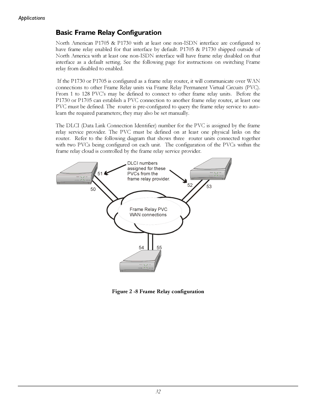
The DLCI (Data Link Connection Identifier) number for the PVC is assigned by the frame relay service provider. The PVC must be defined on at least one physical links on the router. Refer to the following diagram that shows three router units connected together with two PVCs being configured on each unit. The configuration of the PVCs within the frame relay cloud is controlled by the frame relay service provider.
| DLCI numbers |
|
| assigned for these |
|
51 | PVCs from the |
|
| frame relay provider. |
|
50 | 52 | 53 |
|
|
![]()
![]()
![]() Frame
Frame![]() Relay PVC
Relay PVC![]()
![]()
WAN connections
54
55
Figure 2 -8 Frame Relay configuration
32