Servicing Information
Installing the ISDN Link Modules
If there is an ISDN module plus another type of WAN interface module or if there is a single ISDN module, the ISDN U or S/T Module must only be installed in the Slot 1 position. The slot 2 position may contain another type of WAN module or may be unused and covered with a blank panel. For P1730 models, if there is a second LAN module in this unit, it must go in the Slot 1 position and the ISDN module in Slot 2.
Note: the older double width type ISDN module will not fit in this device.
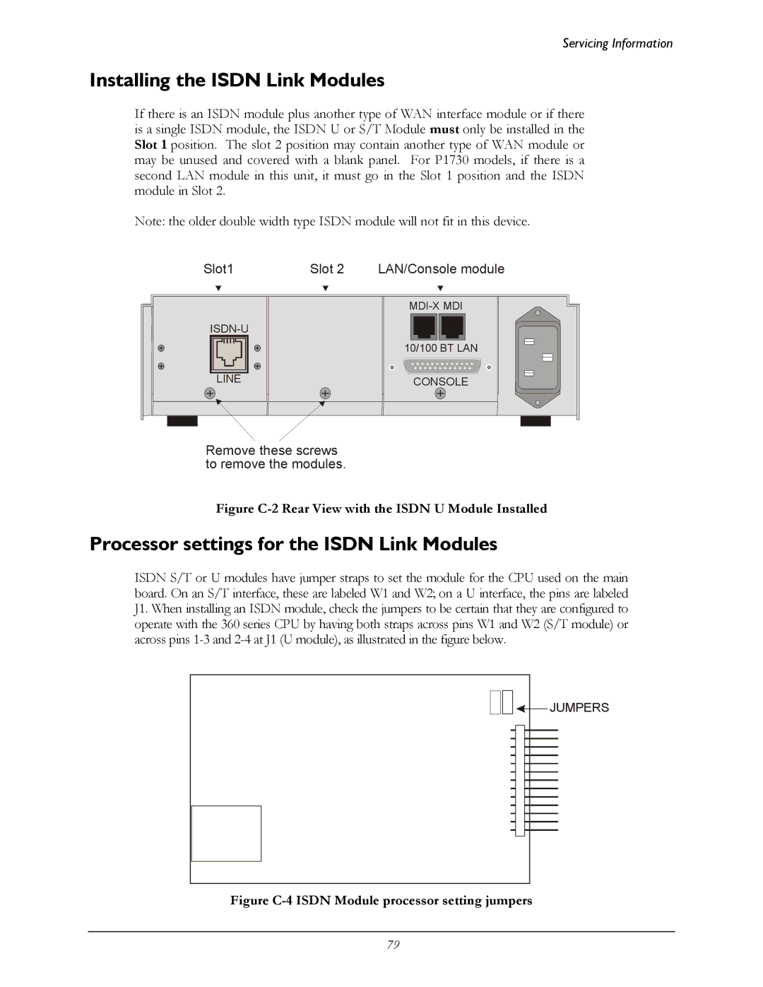
Slot1 | Slot 2 | LAN/Console module |
|
| |
|
| |
|
| 10/100 BT LAN |
LINE |
| CONSOLE |
Remove these screws to remove the modules.
Figure C-2 Rear View with the ISDN U Module Installed
Processor settings for the ISDN Link Modules
ISDN S/T or U modules have jumper straps to set the module for the CPU used on the main board. On an S/T interface, these are labeled W1 and W2; on a U interface, the pins are labeled J1. When installing an ISDN module, check the jumpers to be certain that they are configured to operate with the 360 series CPU by having both straps across pins W1 and W2 (S/T module) or across pins
![]()
![]() JUMPERS
JUMPERS
Figure C-4 ISDN Module processor setting jumpers
79