Philips HDTV user manual Connecting a Hdtv Decoder Set-Top Box, Connecting a VCR, Using RGB Input

Models: HDTV

1 59
Download 59 pages 24.39 Kb
Page 16
Image 16

User Manual BDH5011

7.2Connecting a HDTV Decoder Set-Top Box

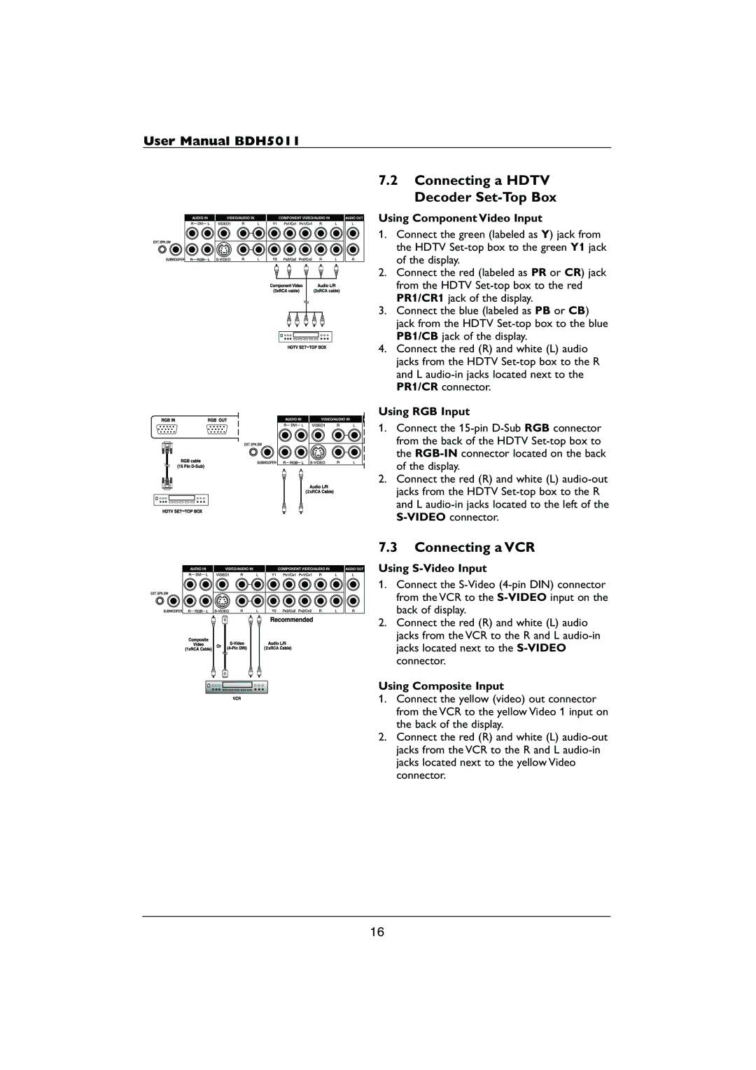
Using Component Video Input

1.Connect the green (labeled as Y) jack from the HDTV Set-top box to the green Y1 jack of the display.

2.Connect the red (labeled as PR or CR) jack from the HDTV Set-top box to the red PR1/CR1 jack of the display.

3.Connect the blue (labeled as PB or CB) jack from the HDTV Set-top box to the blue PB1/CB jack of the display.

4.Connect the red (R) and white (L) audio jacks from the HDTV Set-top box to the R and L audio-in jacks located next to the PR1/CR connector.

Using RGB Input

1.Connect the 15-pin D-Sub RGB connector from the back of the HDTV Set-top box to the RGB-INconnector located on the back of the display.

2.Connect the red (R) and white (L) audio-out jacks from the HDTV Set-top box to the R and L audio-in jacks located to the left of the S-VIDEOconnector.

7.3Connecting a VCR

Using S-Video Input

1.Connect the S-Video (4-pin DIN) connector from the VCR to the S-VIDEOinput on the back of display.

2.Connect the red (R) and white (L) audio jacks from the VCR to the R and L audio-in jacks located next to the S-VIDEOconnector.

Using Composite Input

1.Connect the yellow (video) out connector from the VCR to the yellow Video 1 input on the back of the display.

2.Connect the red (R) and white (L) audio-out jacks from the VCR to the R and L audio-in jacks located next to the yellow Video connector.

16

Page 16
Image 16
Philips HDTV user manual Connecting a Hdtv Decoder Set-Top Box, Connecting a VCR, Using RGB Input, Using Composite Input