Connector pin wiring
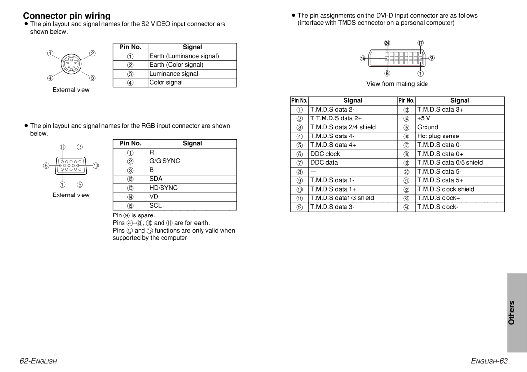
BThe pin layout and signal names for the S2 VIDEO input connector are shown below.
BThe pin assignments on the
#$
&%
External view
Pin No. | Signal |
#Earth (Luminance signal) $ Earth (Color signal)
% Luminance signal & Color signal
:3
2![]()
![]()
![]()
![]()
![]() +
+
* #
View from mating side
BThe pin layout and signal names for the RGB input connector are shown below.
Pin No. | Signal | Pin No. | Signal |
# | T.M.D.S data 2- | / | T.M.D.S data 3+ |
|
|
| |
$ T T.M.D.S data 2+ | 0 | +5 V | |
|
|
| |
% T.M.D.S data 2/4 shield | 1 | Ground | |
|
|
|
|
& | T.M.D.S data 4- | 2 | Hot plug sense |
-1
(,
#'
External view
Pin No. | Signal |
|
|
# | R |
|
|
$ | G/G·SYNC |
|
|
% | B |
|
|
. | SDA |
|
|
/ | HD/SYNC |
|
|
0 | VD |
|
|
1 | SCL |
|
|
Pin + is spare.
Pins
Pins . and 1 functions are only valid when supported by the computer
' | T.M.D.S data 4+ | 3 | T.M.D.S data 0- |
( | DDC clock | 4 | T.M.D.S data 0+ |
|
|
|
|
) | DDC data | 5 | T.M.D.S data 0/5 shield |
|
|
|
|
* | - | 6 | T.M.D.S data 5- |
|
|
|
|
+ | T.M.D.S data 1- | 7 | T.M.D.S data 5+ |
|
|
|
|
, | T.M.D.S data 1+ | 8 | T.M.D.S clock shield |
|
|
|
|
- | T.M.D.S data1/3 shield | 9 | T.M.D.S clock+ |
|
|
|
|
. | T.M.D.S data 3- | : | T.M.D.S clock- |
Others