STARTER BOX TO BASE
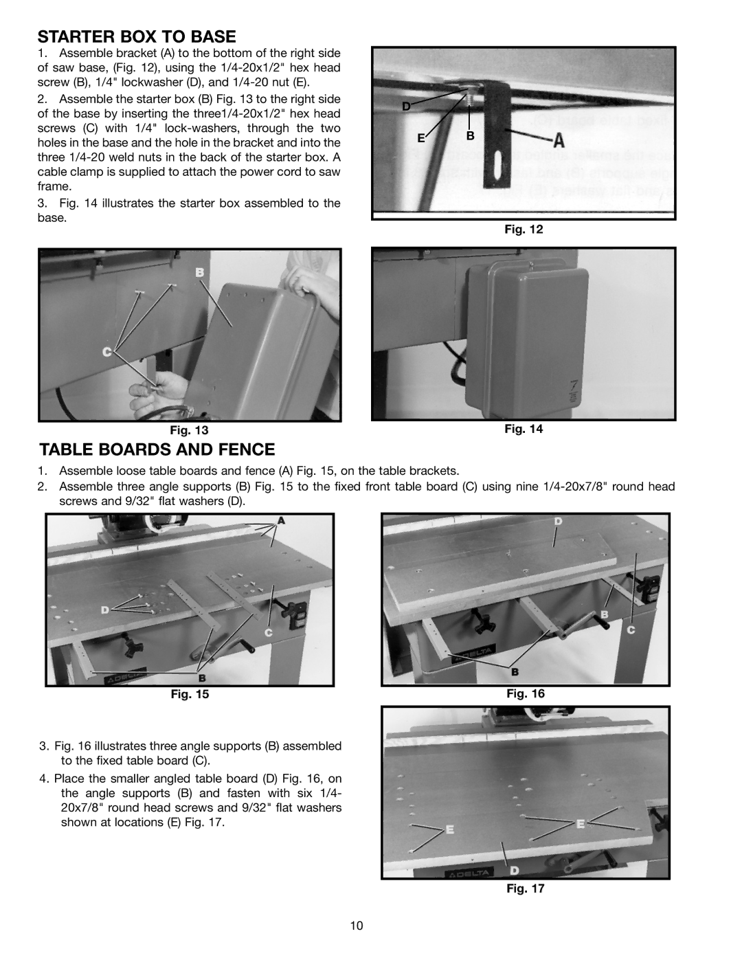
1.Assemble bracket (A) to the bottom of the right side of saw base, (Fig. 12), using the
2.Assemble the starter box (B) Fig. 13 to the right side of the base by inserting the
3.Fig. 14 illustrates the starter box assembled to the base.
D
E B
Fig. 12
Fig. 13 | Fig. 14 |
TABLE BOARDS AND FENCE
1.Assemble loose table boards and fence (A) Fig. 15, on the table brackets.
2.Assemble three angle supports (B) Fig. 15 to the fixed front table board (C) using nine
Fig. 15 | Fig. 16 |
3.Fig. 16 illustrates three angle supports (B) assembled to the fixed table board (C).
4.Place the smaller angled table board (D) Fig. 16, on the angle supports (B) and fasten with six 1/4- 20x7/8" round head screws and 9/32" flat washers shown at locations (E) Fig. 17.
Fig. 17
10