3.IMPORTANT: To prevent arbor nut from spinning when blade stops, place the
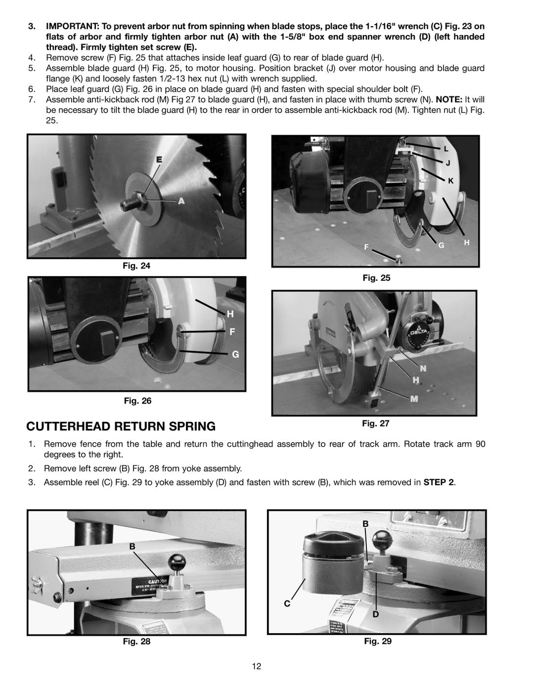
4.Remove screw (F) Fig. 25 that attaches inside leaf guard (G) to rear of blade guard (H).
5.Assemble blade guard (H) Fig. 25, to motor housing. Position bracket (J) over motor housing and blade guard flange (K) and loosely fasten
6.Place leaf guard (G) Fig. 26 in place on blade guard (H) and fasten with special shoulder bolt (F).
7.Assemble
Fig. 24
H
F
G
Fig. 26
L
J
K
FG H
Fig. 25
CUTTERHEAD RETURN SPRING | Fig. 27 |
1.Remove fence from the table and return the cuttinghead assembly to rear of track arm. Rotate track arm 90 degrees to the right.
2.Remove left screw (B) Fig. 28 from yoke assembly.
3.Assemble reel (C) Fig. 29 to yoke assembly (D) and fasten with screw (B), which was removed in STEP 2.
B
B
C
D
Fig. 28 | Fig. 29 |
12