ADJUSTING TABLE TOP
PARALLEL TO TRACK-ARM
For accurate work the
To check and adjust:
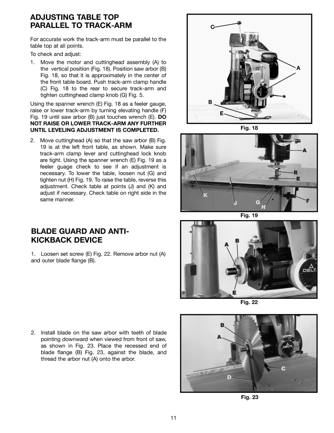
1.Move the motor and cuttinghead assembly (A) to the vertical position (Fig. 18). Position saw arbor (B) Fig. 18, so that it is approximately in the center of the front table board. Push
(C)Fig. 18 to the rear to secure track-arm and tighten cuttinghead clamp knob (G) Fig. 5.
Using the spanner wrench (E) Fig. 18 as a feeler gauge, raise or lower track-arm by turning elevating handle (F) Fig. 19 until saw arbor (B) just touches wrench (E). DO
NOT RAISE OR LOWER
2.Move cuttinghead (A) so that the saw arbor (B) Fig. 19 is at the left front table, as shown. Make sure
BLADE GUARD AND ANTI-
KICKBACK DEVICE
1.Loosen set screw (E) Fig. 22. Remove arbor nut (A) and outer blade flange (B).
2.Install blade on the saw arbor with teeth of blade pointing downward when viewed from front of saw, as shown in Fig. 23. Place the recessed end of blade flange (B) Fig. 23, against the blade, and thread the arbor nut (A) onto the arbor.
C![]()
![]() A
A
B
E
Fig. 18
F
Fig. 19
Fig. 22
Fig. 23
11