ADJUSTING BLADE SQUARE WITH TABLE TOP
DISCONNECT MACHINE FROM POWER
SOURCE.
1.Remove blade guard and place saw blade in
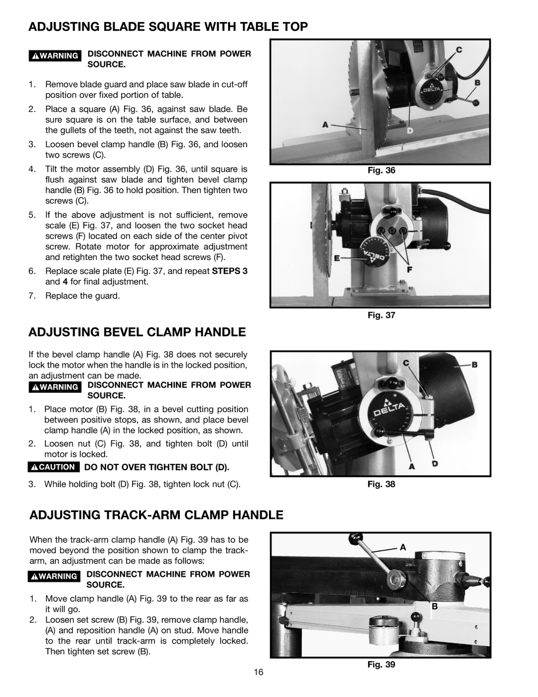
2.Place a square (A) Fig. 36, against saw blade. Be sure square is on the table surface, and between the gullets of the teeth, not against the saw teeth.
3.Loosen bevel clamp handle (B) Fig. 36, and loosen two screws (C).
4.Tilt the motor assembly (D) Fig. 36, until square is flush against saw blade and tighten bevel clamp handle (B) Fig. 36 to hold position. Then tighten two screws (C).
5.If the above adjustment is not sufficient, remove scale (E) Fig. 37, and loosen the two socket head screws (F) located on each side of the center pivot screw. Rotate motor for approximate adjustment and retighten the two socket head screws (F).
6.Replace scale plate (E) Fig. 37, and repeat STEPS 3 and 4 for final adjustment.
7.Replace the guard.
ADJUSTING BEVEL CLAMP HANDLE
If the bevel clamp handle (A) Fig. 38 does not securely lock the motor when the handle is in the locked position, an adjustment can be made.
DISCONNECT MACHINE FROM POWER
SOURCE.
1.Place motor (B) Fig. 38, in a bevel cutting position between positive stops, as shown, and place bevel clamp handle (A) in the locked position, as shown.
2.Loosen nut (C) Fig. 38, and tighten bolt (D) until motor is locked.
![]() DO NOT OVER TIGHTEN BOLT (D).
DO NOT OVER TIGHTEN BOLT (D).
3. While holding bolt (D) Fig. 38, tighten lock nut (C).
Fig. 36
Fig. 37
Fig. 38
ADJUSTING TRACK-ARM CLAMP HANDLE
When the
DISCONNECT MACHINE FROM POWER
SOURCE.
1.Move clamp handle (A) Fig. 39 to the rear as far as it will go.
2.Loosen set screw (B) Fig. 39, remove clamp handle,
(A) and reposition handle (A) on stud. Move handle to the rear until
A
B
Fig. 39
16