GUIDE TO PARTS
The following is an explanation of the operating controls of the Delta 14", 16" and 18" Radial Arm Saws. All users will benefit by knowing how to set and operate the controls for all cutting operations. To avoid the possibility of damage to the machine and/or injury to the operator, all user’s should become familiar with the operations and the controls before turning the machine “ON’.
A
B
M
E
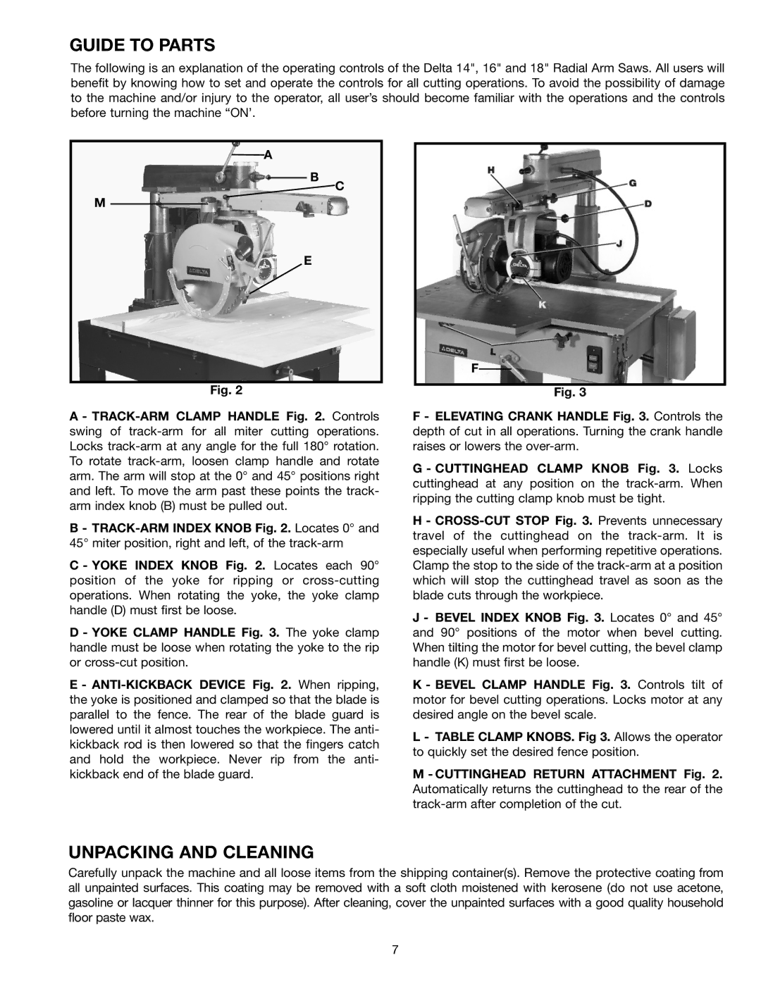
Fig. 2
C
F
Fig. 3
A -
B -
C - YOKE INDEX KNOB Fig. 2. Locates each 90° position of the yoke for ripping or
D - YOKE CLAMP HANDLE Fig. 3. The yoke clamp handle must be loose when rotating the yoke to the rip or
E -
F - ELEVATING CRANK HANDLE Fig. 3. Controls the depth of cut in all operations. Turning the crank handle raises or lowers the
G - CUTTINGHEAD CLAMP KNOB Fig. 3. Locks cuttinghead at any position on the
H -
J - BEVEL INDEX KNOB Fig. 3. Locates 0° and 45° and 90° positions of the motor when bevel cutting. When tilting the motor for bevel cutting, the bevel clamp handle (K) must first be loose.
K - BEVEL CLAMP HANDLE Fig. 3. Controls tilt of motor for bevel cutting operations. Locks motor at any desired angle on the bevel scale.
L - TABLE CLAMP KNOBS. Fig 3. Allows the operator to quickly set the desired fence position.
M - CUTTINGHEAD RETURN ATTACHMENT Fig. 2. Automatically returns the cuttinghead to the rear of the
UNPACKING AND CLEANING
Carefully unpack the machine and all loose items from the shipping container(s). Remove the protective coating from all unpainted surfaces. This coating may be removed with a soft cloth moistened with kerosene (do not use acetone, gasoline or lacquer thinner for this purpose). After cleaning, cover the unpainted surfaces with a good quality household floor paste wax.
7