![]()
![]()
![]()
![]()
![]()
![]()
![]()
![]() TM
TM
APP. A STAR …
CODES (HEX/CONTROL) : 1B 26 00 n1 n2 / <ESC> “&” <0> n1 n2
When 15 CPI character size is set (default setting), the detail of the code is :
1B 26 00 n1 n2 [m0 m1 m2 m3 m4 m5 m6
When 8 CPI or 12 CPI character size is set, the detail of the code is :
1B 26 00 n1 n2 [m0 m1 m2 m3 m4
m2 m3 m4
FUNCTION : Definition of download characters
DEFINITION RANGE : 21H ≤ n1 ≤ n2 ≤ 7FH, m0 = 00H or 80H
APPLICATION LIMIT : When the 15 CPI character size is set (the default setting), printing of adjacent horizontal dots is not allowed.
DETAIL DESCRIPTION : Defines download characters from host computer. Up to 10 download characters can be defined and the defined character patterns can be stored in the printer’s memory. Definitions of the variables in the command code are as follows:
n1 and n2 represent the starting address and the ending address of the range of download characters respectively. When defining only one character, n1 = n2.
Each set of m0 to m7 (for 7 x 9 fonts) or m0 to m5 (for 5 x 9 fonts) defines one download character. However, only either top 8 or bottom 8 print pins out of total 9 print pins of the print head can be used. m0 defines which set of pins to be used.
m1 to m7 or m1 to m5 indicates each column of the download character pattern consecutively. Each bit in m1 to m7 or m1 to m5 defines a dot within that column to be printed (in vertical position). The relationship of each bit with each print pin combined with m0 can be illustrated in the following table, where the print pin # starts count at 1 from top of the print head:
bit # of m1 to m7 or m1 to m5 | 8 (MSB) | 7 | 6 | 5 | 4 | 3 | 2 | 1 (LSB) |
|
|
|
|
|
|
|
|
|
engage print pin # (when m0 = 00h) | 2 | 3 | 4 | 5 | 6 | 7 | 8 | 9 |
|
|
|
|
|
|
|
|
|
engage print pin # (when m0 = 80h) | 1 | 2 | 3 | 4 | 5 | 6 | 7 | 8 |
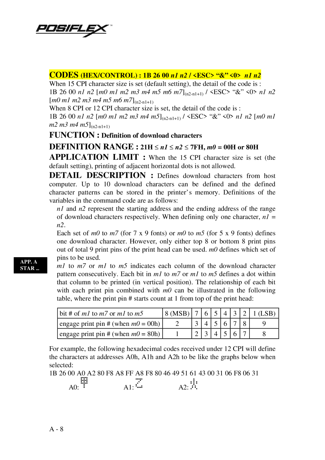
For example, the following hexadecimal codes received under 12 CPI will define the characters at addresses A0h, A1h and A2h to be like the graphs below when selected:
1B 26 00 A0 A2 80 F8 A8 FF A8 F8 80 46 49 51 61 43 00 31 06 F8 06 31
A0: ![]() A1:
A1: ![]()
![]()
![]()
![]()
![]() A2:
A2: ![]()
![]()
![]()
![]()
A - 8
