![]()
![]()
![]()
![]()
![]()
![]()
![]()
![]() TM
TM
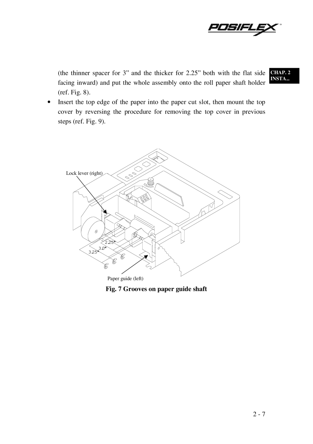
(the thinner spacer for 3” and the thicker for 2.25” both with the flat side facing inward) and put the whole assembly onto the roll paper shaft holder (ref. Fig. 8).
∙Insert the top edge of the paper into the paper cut slot, then mount the top cover by reversing the procedure for removing the top cover in previous steps (ref. Fig. 9).
Lock lever (right)
2.25" ![]()
![]()
3.0"
3.25"
CHAP. 2
INSTA…
Paper guide (left)
Fig. 7 Grooves on paper guide shaft
2 - 7
