Connecting to a Video Source
Available for video models only.
1 . Input signal specifications
Luminance signal | ||||
Chrominance signal | ||||
|
| |||
|
|
|
| |
VIDEO signal |
| |||
|
|
|
| |
AUDIO signal | Input |
| 200mVrms, 20 kΩ below (MAX | |
|
|
| ||
Output |
| 0~200mVrms, 1k Ω | ||
|
| |||
|
|
|
| |
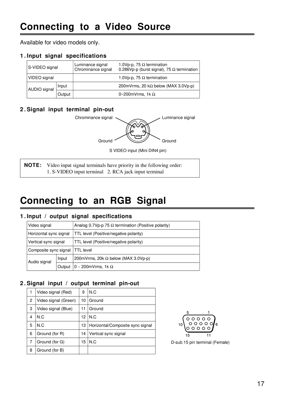
2 . Signal input terminal
Chrominance signal | Luminance signal |
GroundGround
S VIDEO input (Mini DIN4 pin)
NOTE: Video input signal terminals have priority in the following order: 1.
Connecting to an RGB Signal
1 . Input / output signal specifications
Video signal | Analog | ||
|
|
| |
Horizontal sync signal | TTL level (Positive/negative polarity) | ||
|
|
| |
Vertical sync signal | TTL level (Positive/negative polarity) | ||
|
|
| |
Composite sync signal | TTL level | ||
|
|
| |
Audio signal | Input | 200mVrms, 20k Ω below (MAX | |
|
| ||
Output | 0 ∼ 200mVrms, 1k Ω | ||
| |||
|
|
| |
2 . Signal input / output | terminal |
| ||
1 | Video signal (Red) | 9 | N.C |
|
2 | Video signal (Green) | 10 | Ground |
|
3 | Video signal (Blue) | 11 | Ground |
|
4 | N.C | 12 | N.C |
|
5 | N.C | 13 | Horizontal/Composite sync signal | |
6 | Ground (for R) | 14 | Vertical sync signal | |
7 | Ground (for G) | 15 | N.C | |
8 | Ground (for B) |
|
|
|
17