QLogic HCA and QLogic Ofed Software Install Guide
Document Revision History
Preliminary
Preliminary
Removed phrase and Transmission Control
Moved table InfiniPath and OpenFabrics
Ipathether Configuration Setup Gener
Ates Error
Removed note OpenFabrics programs 32-bit
Preliminary
Table of Contents
Software Installation
Installation Verification and Additional Settings
Write Combining
List of Figures
Preliminary
How this Guide is Organized
Introduction
Who Should Read this Guide
Overview
Typographical Conventions
Interoperability
Conventions Used in this Guide
Meaning
Documentation
Product documentation includes
Contact Information
Support Headquarters
Preliminary
Feature Overview
Features
Other Changes
Support
QLogic Adapter Model Numbers
Description
Software Components
„ Ofed SRP
Step-by-Step Installation Checklist
Hardware Installation
Software Installation
Preliminary
Preliminary
Hardware
Hardware Installation
Hardware Installation Requirements
Adapter Models and Related Platforms
Form Factors
Run ipath control
Product Number Description
Cabling and Switches
QLogic InfiniBand Cables
Configuring the Bios
List of the Package Contents
Safety with Electricity
Verify the Package Contents
Unpacking Information
Hardware Installation Unpacking Information
QLogic QLE7280 with IBA7220 Asic
Unpacking the QLogic Adapter
Asic
Dual Adapter Installation
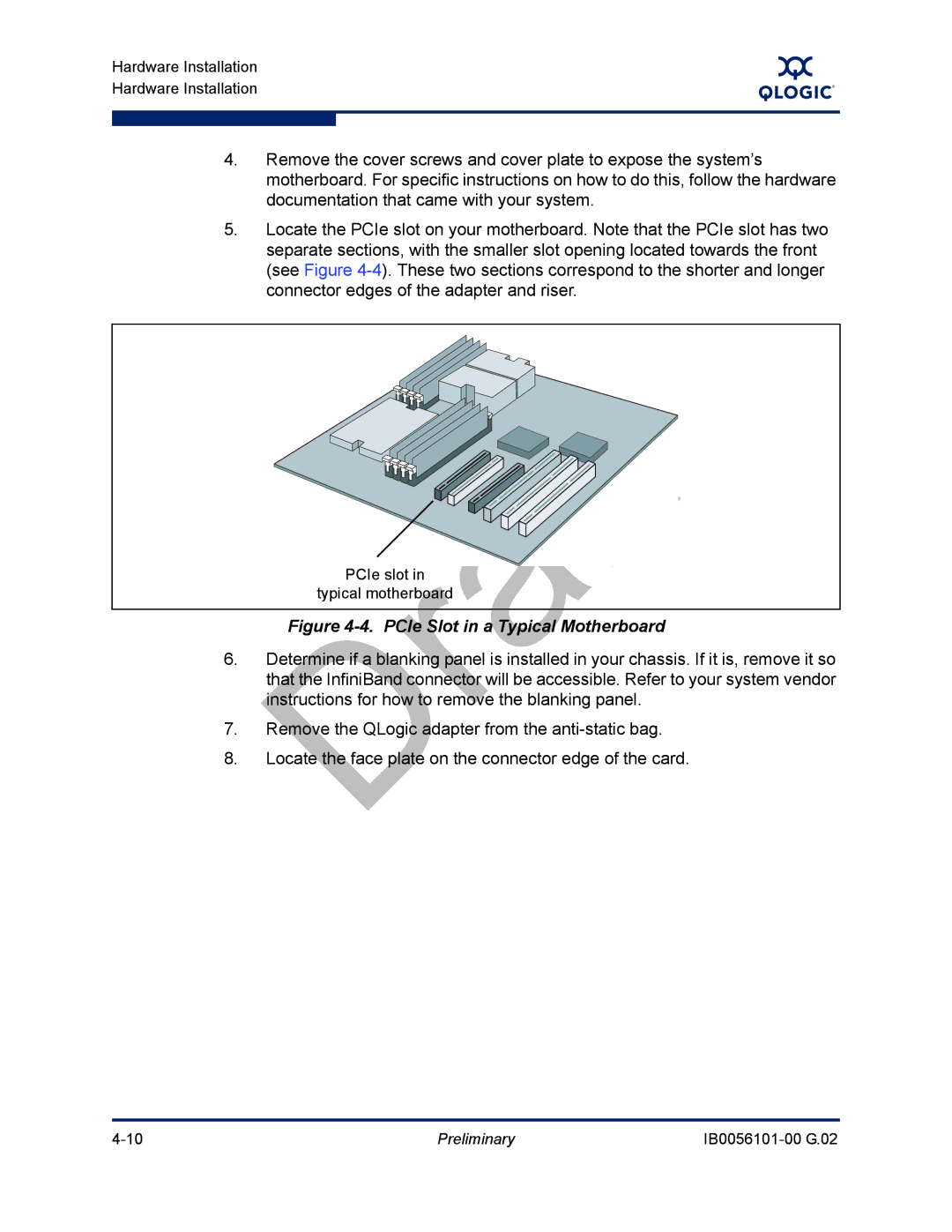
PCIe Slot in a Typical Motherboard
QLogic PCIe HCA Assembly with Riser Card
Hardware Installation for QHT7140 with HTX Riser
Assembled PCIe HCA with Riser
HTX Slot
QLogic QHT7140 Adapter with Riser Card
Assembled QHT7140 with Riser
Hardware Installation for the QHT7140 Without an HTX Riser
Switch Configuration and Monitoring
Cabling the Adapter to the InfiniBand Switch
Completing the Installation
Types of Nodes in a Cluster Environment
Software Installation
Cluster Setup
Supported Linux Distributions
Distribution InfiniPath/OpenFabrics Supported Kernels
Distribution Identifiers
InfiniPath/OpenFabrics Supported Distributions and Kernels
Distribution Identifiers
Rhel5
Setting Up Your Environment
Compiler Support
Sles10
OS Distribution Required Packages
Choose the Appropriate Download Files
Required OS Packages
Specific Component Requirements
Package Description Installation Documentation
Available Packages for QLogic Ofed 1.4 Release
Install InfiniPath and OpenFab
Install QLogicIB-Basic with the Installer Tool
Kit on
You will see a screen similar to this
Ofed SDP
Next screen contains these choices
Then type n to proceed to the next screen
# ./INSTALL --32bit
Configure Ofed IP over IB IPV4 addresses now? n
Command Meaning
Install -Clists all the available components, which include
Install Options
Additional component names allowed for -Eand -Doptions
About rpm Installation
Using rpm to Install InfiniPath and OpenFabrics
Become root, then
Next, install all non-prefixed RPMs
RPM Organization
Install QLogic Ofed User-level Software with the rpm Command
Finally, install the prefixed RPMs in /usr/mpi/qlogic
Software Installation
Install QLogic Ofed Using Rocks
Install Frontend and Compute Nodes
Rocks Installation on an Existing Frontend Node
Then use the following command for each node
Install QLogic Ofed Using a Platform OCS Kit
Install FastFabric Software CD/ISO Image
Use the following command to rebuild the entire cluster
Installing Lustre
Install Additional Software
Installed Layout
MPI include files are
Removing Software Packages
Uninstalling Using the Installer Tool
Uninstalling InfiniPath and OpenFabrics RPMs
Qlc is a part of all the InfiniPath package names
Uninstalling Software with Rocks or Platform OCS
Downgrading RPMs
Preliminary
InfiniPath and OpenFabrics Driver Overview
Configuring Drivers and Services
OpenFabrics Drivers and Services Configuration and Startup
Output from this command will be similar to this
Configuring the IPoIB Network Interface
To verify the configuration, type
Type
Command to disable it on reboot is
OpenSM
Etc/init.d/opensmd
You can stop opensmd again like this
To use Ofed SRP, follow these steps
Output, look for lines similar to these
Guid
Configuring and Administering the Vnic Interface
# ibqlgcvnicquery
Preliminary
Create the Vnic interfaces using the configuration file
Etc/infiniband/qlgcvnic.cfg
RX CSUM=TRUE HEARTBEAT=100
Preliminary
To restart the QLogic Vnic driver, run the following command
MPI over uDAPL
This information is collected from
Other Configuration Changing the MTU Size
On every node, type the following command as root
Managing the InfiniPath Driver
Etc/infiniband/openib.conf
Start, Stop or Restart InfiniPath
Configure InfiniPath Driver State
To enable the driver, use the command as root
Device files are
Unloading the Driver/Modules Manually
Further Information on Configuring and Loading Drivers
Sequence of commands to restart the driver are as follows
Preliminary
Adapter and Other Settings
Installation Verification and Additional Settings
LED Link and Data Indicators
Hostname1 Hostname2
Customer Acceptance Utility
This will also show link speed
Ipath checkout Options
Preliminary
Node Spontaneously Reboots
Installation Troubleshooting
Hardware Issues
Some HTX Motherboards May Need Two or More CPUs in Use
Enable Advanced Configuration and Power Interface Acpi
Bios Settings
Software Installation Issues
Issue with Supermicro H8DCE-HTe and QHT7040
# yum install kernel-devel
Mpirun Installation Requires 32-bit Support
Resolving Conflicts
Outdated ipathether Configuration Setup Generates Error
Configuration Issues
Lockable Memory Error on Initial Installation of InfiniPath
Check your distribution for the exact RPM name
Eth2 error fetching interface information Device not found
Verify Write Combining is Working
Write Combining
Introduction
Mtrr Mapping and Write Combining
Edit Bios Settings to Fix Mtrr Issues
PAT and Write Combining
Use the ipathmtrr Script to Fix Mtrr Issues
Preliminary
Configuration File Name Description
Configuration Files
Table C-1. Configuration Files
With the Ofed documentation, or
Also installed in /etc/infiniband
Sample and Template Files Description
Qlgcvnictools subdirectory
Different Nodes May Use Different RPMs
Package Descriptions
Package Names with the QLogicIB-Basic Download
InfiniPath and OpenFabrics RPMs
InfiniPath RPM Version Numbers and Identifiers
OpenFabrics RPM Names
Table D-1. Documentation/RPMs
Documentation RPMs
InfiniPath RPMs
Table D-2. InfiniPath/RPMs
Table D-4. InfiniPath-MPI/RPMs
OpenFabrics RPMs
Table D-3. InfiniPath-Devel/RPMs
Table D-5. OpenFabrics/RPMs
Ibsim-xxx.x8664.rpm
Dapl-xxx.x8664.rpm
Dapl-utils-xxx.x8664.rpm
Ibutils-xxx.x8664.rpm
Libipathverbs-xxx.x86 64.rpm
Libibverbs-xxx.x8664.rpm
Libibverbs-utils-xxx.x8664.rpm
Librdmacm-xxx.x86 64.rpm
Table D-6. OpenFabrics-Devel/RPMs
Table D-7. OpenSM/RPM
Table D-9. Other HCAs/RPMs
Other HCAs
Table D-8. OpenSM-Devel/RPM
Table D-10. Other HCAs-Devel/RPMs
Other MPIs
Table D-11. OtherMPIs/RPMs
Openmpiintelqlc-xxx.yyy.x8664.rpm a
Openmpigcc-xxx.x8664.rpm
Openmpigccqlc-xxx.yyy.x8664.rpm
Openmpipathscaleqlc-xxx.yyy.x8664.rpm
Preliminary
Form factors for HCAs Hardware installation overview
Index
Module
Hardware requirements
HTX motherboards may required two or more CPUs A-1
Mpi-selector 5-15,5-18
VNIC, configuration
Skip=LIST 7-3Software
Page
Preliminary